
Power supply system

Inactive Publication Date: 2022-04-14
LS ELECTRIC CO LTD
View PDF0 Cites 0 Cited by
  • Summary
  • Abstract
  • Description
  • Claims
  • Application Information

AI Technical Summary

Benefits of technology

The power supply system described in this patent is designed to effectively supply power to a load in various abnormal situations. This solution can overcome the limitations of existing power supply systems and improve their performance.

Problems solved by technology

However, when the system is configured in this way, is there are limitations such as system stability problem, difficulty in controlling power reception and supply, and a lack of countermeasures in case of an accident.
Since a large number of power devices having a complex configuration are provided, system operation cannot be stably carried out when compatibility between devices is poor.
Furthermore, when a load to which each device supplies power is a critical load that needs power supply at all times, it may be required to provide a separate UPS device for an abnormal condition, but when a UPS device is provided, the configuration of the system becomes more complicated, and the provision of the UPS device itself may not be easy due to structural / design constraints.
In addition, as the configuration becomes more complicated, the control of each device and system may be inevitably more complex, and the risk of occurrence of failures and accidents may increase.
As a result, it may be difficult to supply stable and reliable power, so the operation of the load may be also unstable, and an appropriate operational response to the occurrence of various accidents cannot be made.
In one embodiment, a case where the power supply is interrupted may be when the state of at least one of the at least one power supply source that supplies power to the plurality of power panels, the DC power of the plurality of power panels, the driving power, the at least one first power conversion device, and the load is changed to cause an abnormality in the supply of the driving power to the load.
However, the technology disclosed in this specification may not be limited thereto, and may be applied and implemented to all power devices, power supply devices, power control devices, power supply systems, power systems, power control systems, plant systems, plant control systems, plant control methods, energy storage systems, control methods or operation methods of the energy storage systems, and motor control panels that control a plurality of motor loads, motor control systems, motor operation systems, and the like.

Method used


Image

  • Power supply system
  • Power supply system
  • Power supply system

Examples


Embodiment Construction

[0084]It should be noted that technological terms used herein are merely used to describe a specific embodiment, but not to limit the concept of the technology disclosed in the present specification. Also, unless particularly defined otherwise, technological terms used herein should be construed as a meaning that is generally understood by those having ordinary skill in the field to which the technology disclosed in the present specification belongs, and should not be construed too broadly or too narrowly. Furthermore, if technological terms used herein are wrong terms that are unable to correctly express the concept of the technology disclosed in the present specification, then they should be replaced by technical terms that are properly understood by those skilled in the art. In addition, general terms used in the present specification should be construed based on the definition of dictionary, or the context, and should not be construed too broadly or too narrowly.

[0085]In additio...


PUM


Abstract

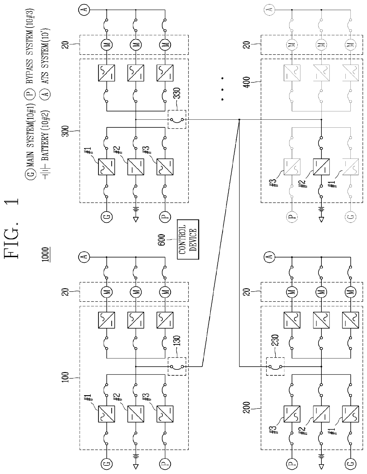
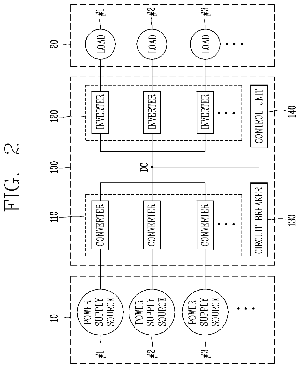
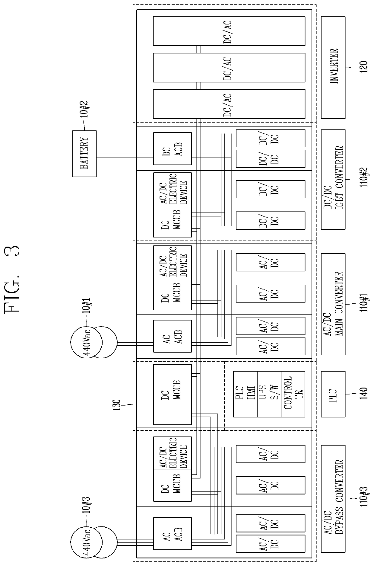
The present specification relates to a power supply system capable of supplying uninterruptible power, the system comprising a plurality of circuit breakers for controlling the connections between a plurality of power source modules, to control power demand and supply through opening or closing of the circuit breakers according to various situations occurring in the system, so as to enable a UPS function between the plurality of power source modules.

Description

BACKGROUND1. Technical Field[0001]The present disclosure relates to a power supply system capable of supplying uninterruptible power.2. Description of the Related Art[0002]The technology behind the present disclosure relates to a system comprising a plurality of power supply devices.[0003]A system in which a plurality of power supply devices supply power to each load may be connected in common through a DC bus line. When connected to a common bus line as described above, there is an advantage capable of receiving and supplying power from and to an adjacent power device through the DC bus line. However, when the system is configured in this way, is there are limitations such as system stability problem, difficulty in controlling power reception and supply, and a lack of countermeasures in case of an accident.[0004]Since a large number of power devices having a complex configuration are provided, system operation cannot be stably carried out when compatibility between devices is poor....

Claims


Application Information

Patent Timeline
IPC IPC(8): H02J9/06
CPCH02J9/062H02J9/06H02J3/007H02J1/12
Inventor PARK, MINJUNYUN, DONGJINKIM, JIHONGKIM, DOHYUNHWANG, KWANGKYU
Owner LS ELECTRIC CO LTD
Learn More