Brake drum measuring and inspecting device

a brake drum and measuring device technology, applied in the direction of mechanical measuring arrangements, instruments, force/torque/work measurement apparatus, etc., can solve the problems of slow wear of the brake drum braking surface, reducing the thickness of the drum wall, and reducing the ability of the drum to absorb and dissipate heat, etc., to achieve the effect of quick determination

Inactive Publication Date: 2013-06-25
HOWER DAVID
View PDF15 Cites 5 Cited by
  • Summary
  • Abstract
  • Description
  • Claims
  • Application Information

AI Technical Summary

Benefits of technology

[0016]It is an object of the present invention, therefore, to provide an apparatus for quickly determining whether or not the inside diameter or braking surface of a brake has reached or exceeded its maximum allowable diameter without removing the wheel and brake drum from the vehicle.

Problems solved by technology

Over time, as the brakes are repeatedly applied, the brake drum braking surfaces are slowly worn.
The force of the brake pad linings against the inside surface of a brake drum causes wear on such surface, and in turn the thickness of the drum wall is decreased, reducing the ability of the drum to absorb and dissipate heat.
If the metal drum is worn too thin, excessive heat buildup can cause drum distortion and weakening.
All brake drums are accorded a maximum wear allowance, or maximum inside diameter, beyond which the drum should be replaced because a vehicle having such drum installed cannot be safely operated.
If the maximum inside diameter of a brake drum is exceeded, the braking force generated by the brakes can be severely compromised.
There is also an unacceptable risk of excessive heat buildup causing brake failure, and the brake lining material will lose its effectiveness with overheating.
One or more drums on a vehicle can also wear more quickly if all of the brakes are not properly balanced or adjusted, since the other wheels must do more than their share of the work required to brake the vehicle, and possibly become damaged by an excessive amount of heat.
A significant drawback of these prior art brake drum inspection tools is that the process of removing each wheel and brake drum from a vehicle, inspecting the drum, and then remounting each wheel and either a new drum or the existing drum, is extremely time consuming, particularly where the vehicle is a tractor trailer or other large vehicle.
Full vehicle inspections are therefore expensive both in terms of the amount of manpower and time spent making such inspections, but also in terms of down time for the vehicle, which is essentially out of service until the inspection is completed and either the existing or replacement drums and wheels are remounted on the vehicle.
The long time required to complete a full inspection also limits the number of inspections that can be performed, which in turn leads to an increased number of potentially unsafe vehicles, including tractor trailers but also transit vehicles such as buses, motorcoaches, and the like, on the roads.
In fact, a large number of highway accidents are known to be caused by faulty brake systems, often at least in part due to overly worn brake drums wherein the maximum inside diameter has been exceeded.
While the above prior art devices may be suitable for their intended use, each has one or more shortcomings which it is believed makes them unacceptable for widespread use by vehicle inspectors.
When mounted on a vehicle axle, the brake drum is of course positioned behind or underneath the wheel, and so the only way to access the inside surface of the brake drum is through an opening facing inwardly on the side opposite the wheel, which is inconvenient and awkward to access.
Thus, using any of the prior art devices to perform an inspection with the brake drum still mounted on the vehicle, particularly along a roadside or the like as opposed to use in a specially designed mechanic's garage, is in practice quite difficult.

Method used


Image

  • Brake drum measuring and inspecting device
  • Brake drum measuring and inspecting device
  • Brake drum measuring and inspecting device

Examples


Embodiment Construction

[0031]The following detailed description is of the best mode or modes of the invention presently contemplated. Such description is not intended to be understood in a limiting sense, but to be an example of the invention presented solely for illustration thereof, and by reference to which in connection with the following description and the accompanying drawings one skilled in the art may be advised of the advantages and construction of the invention.

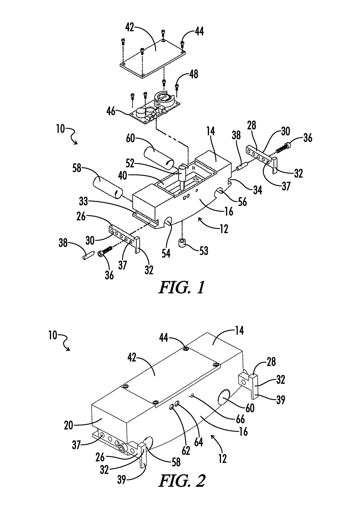
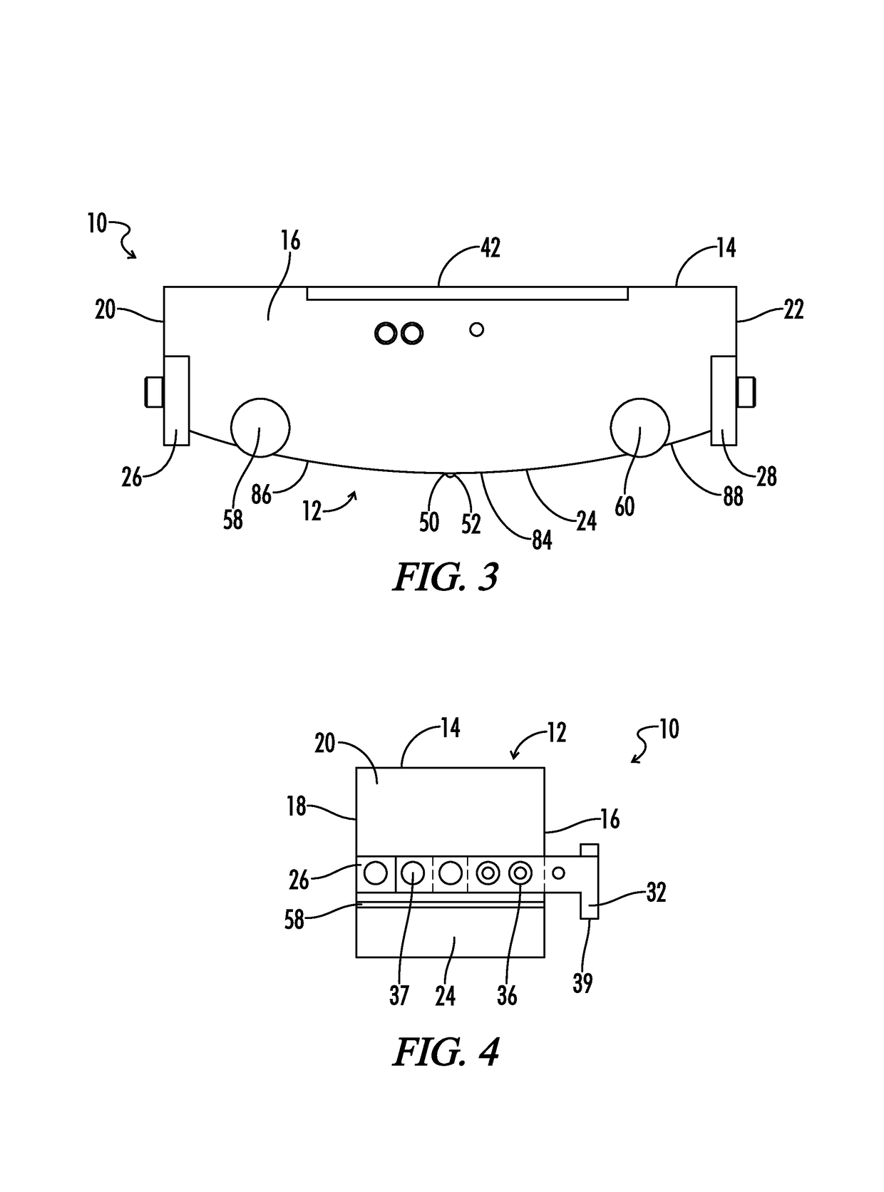
[0032]In the past, it has been problematic for inspections of vehicle brake drums to be performed, and more particularly it is difficult to measure the inside diameter of a brake drum without first requiring complete removal of the wheel and drum from a wheel axle. This limits the number of brake drum inspections that can be performed by certified inspectors, and as a result presents a significant highway safety issue due to an increased number of brake drums that would fail an inspection if one had been performed. In considering the pro...


PUM

PropertyMeasurementUnit
operating distanceaaaaaaaaaa
activating forceaaaaaaaaaa
diameteraaaaaaaaaa

Abstract

An apparatus for inspecting brake drums to quickly determine whether the drums pass or fail inspection comprising a housing dimensioned to be inserted between the brake shoes of a wheel and placed on the inner braking surface of a brake drum, whereby a sensor or switch means is utilized to determine whether or not the inner diameter has exceeded the maximum allowable diameter for such drum, and whereby a visual or audible signal is provided to indicated that the drum has passed or failed inspection.

Description

CROSS REFERENCE TO RELATED APPLICATIONS[0001]This application is based upon and claims priority from U.S. Provisional application Ser. No. 61 / 318,125 filed Mar. 26, 2010, the entirety of which is hereby incorporated by reference.BACKGROUND OF THE INVENTION[0002]1. Field of the Invention[0003]The present invention relates generally to vehicle brake drums, and more particularly to devices and systems for measuring the inside or brake surface diameter of brake drums, and more particularly still to devices and systems for inspecting and measuring the inside or brake surface diameter of a brake drum without requiring removal of the wheel and brake drum from a vehicle wheel axle.[0004]2. Preliminary Discussion and Prior Art[0005]Brake drums are available in various sizes and styles, and are selected for use according to their specifications and depending upon the size and type of vehicle with which a drum is intended to be used, and in particular depending upon the braking force required ...

Claims


Application Information

Patent Timeline
Patent Type & Authority Patents(United States)
IPC IPC(8): G01L5/28G01N3/56G01N19/02
CPCG01B21/14G01B5/0028
Inventor HOWER, DAVID
Owner HOWER DAVID
Why Eureka
Try Eureka