Bed

a technology for beds and beds, applied in the field of beds, can solve the problems of insufficient satisfaction of the functions of caring or hospital-use beds, high physical load on the nurse, the care giver, or the like, and the risk of collision of the person with the side mat plate, etc., to achieve the effect of reducing load, facilitating independence of the cared person, and reducing the burden

Inactive Publication Date: 2013-07-02
PANASONIC CORP
View PDF27 Cites 11 Cited by
  • Summary
  • Abstract
  • Description
  • Claims
  • Application Information

AI Technical Summary

Benefits of technology

[0031]The bed of the present invention makes it possible to safely and swiftly carry out a separating operation or a returning operation from or to the fixed portion of the bed, while a cared person or the like lying thereon is safely kept in a comfortable posture with his or her back or legs being raised, with no member threatening the safety of the cared person being retreated above the bed. Moreover, it is possible to allow the cared person or the like to comfortably lie on the bed and also to move onto a wheel chair from the bed without necessity of moving, as well as to move on the wheel chair safely and comfortably. Therefore, it becomes possible to achieve a bed that reduces load applied to a cared person, that is friendly used by the cared person, and that assists independence of the cared person.

Problems solved by technology

In this case, upon transferring the patient, the cared person, or the like, from the bed onto, for example, a wheel chair, normally, this job is manually carried out by a nurse, a care giver, or the like, with a result that much physical load is imposed on the nurse, the care giver, or the like.
For this reason, issues arise in which, upon or after retreating, a person lying on the bed or the wheel chair receives an oppressive feeling by the retreating side mat plate 4, and in which in a case where the retreating is insufficient, there may be a risk of collision of the person with the side mat plate 4.
Moreover, in most cases, the caring or hospital-use bed is required for providing a back-raised or leg-raised posture state; however, since the above-mentioned conventional bed is not provided by taking the back-raised and leg-raised posture states into consideration, much load is sometimes applied to the cared person or the like, resulting in an issue in which functions as the caring or hospital-use bed are not sufficiently satisfied.

Method used


Image

  • Bed
  • Bed
  • Bed

Examples


first embodiment

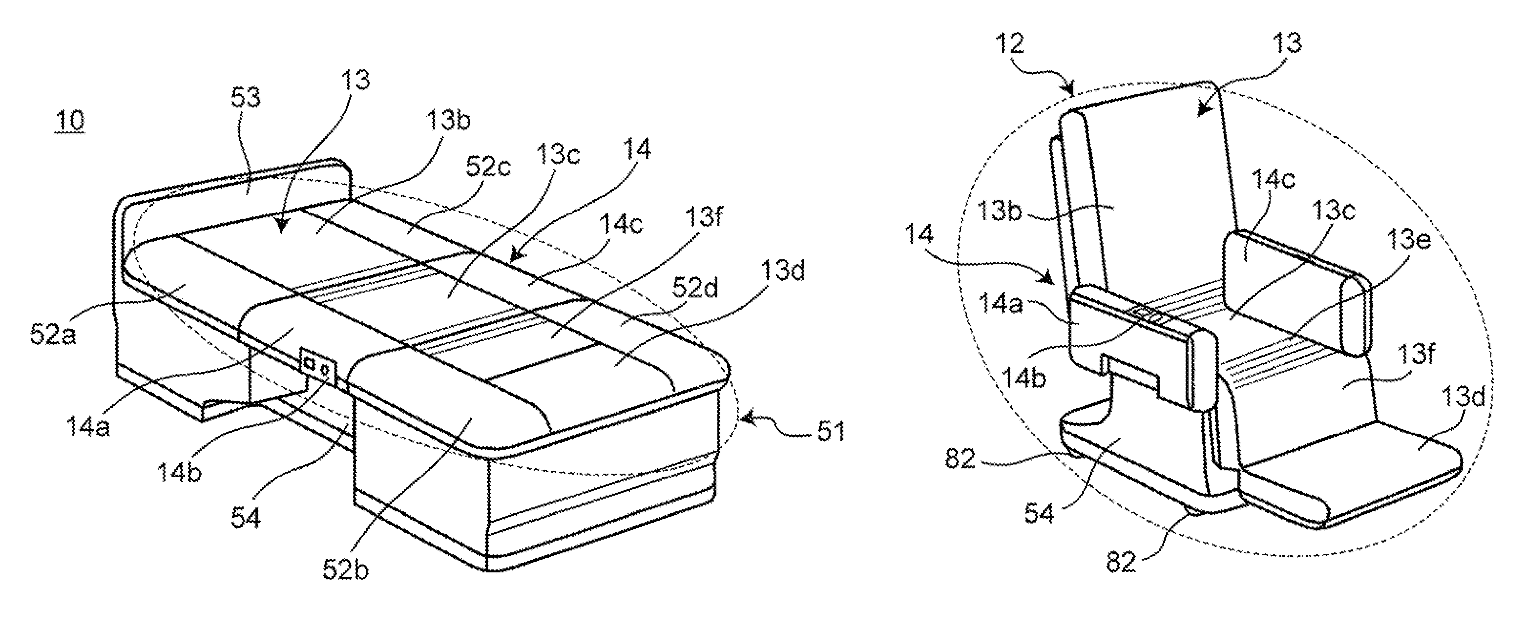
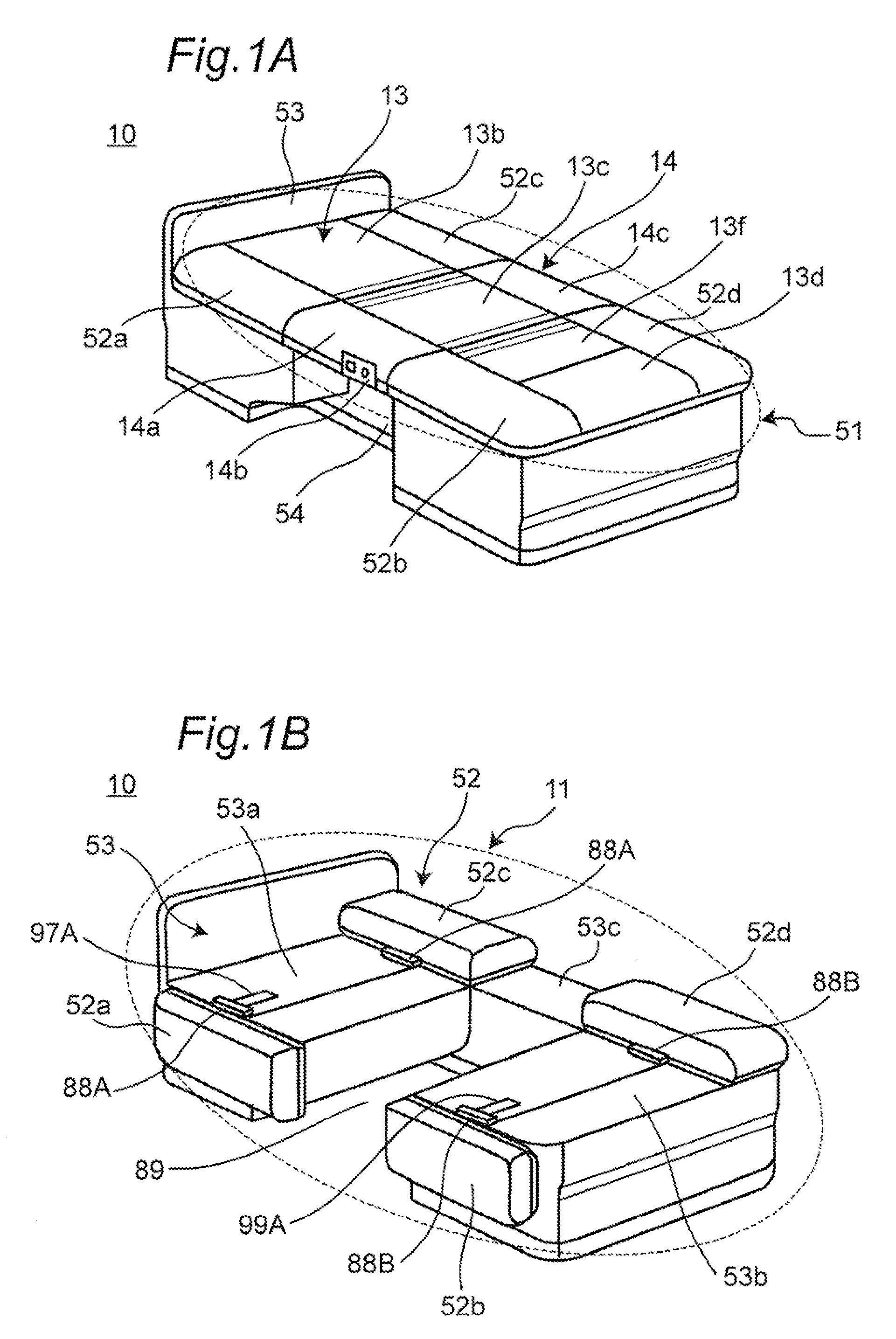
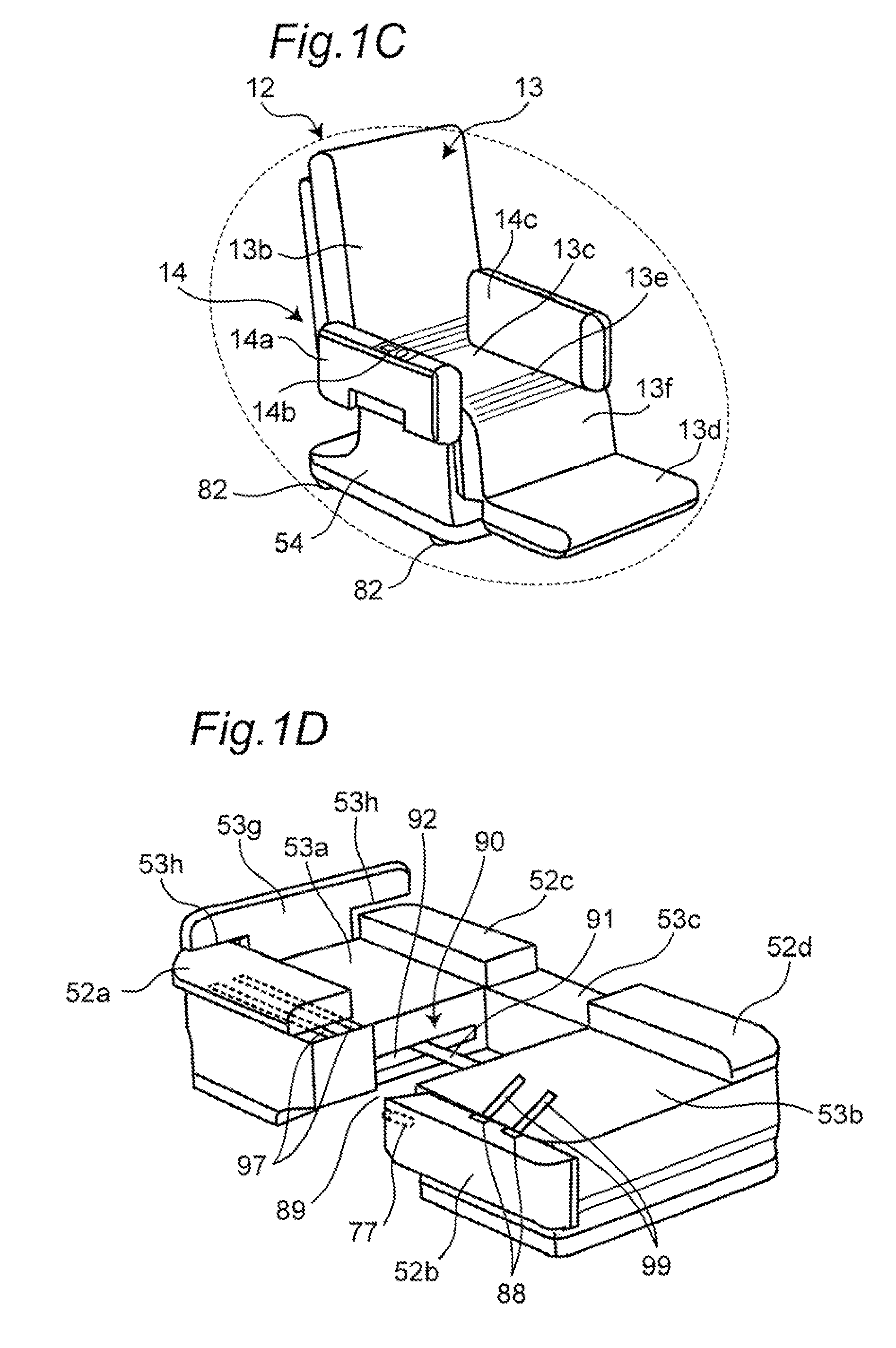
[0058]FIG. 1A shows a schematic structure of a movable bed 10 according to the first embodiment of the present invention, in a perspective view of the movable bed 10 integrally formed by joining a fixed portion 11 and a moving portion 12 with each other. FIG. 1B is a perspective view showing the fixed portion 11 when the movable bed 10 is separated, and FIG. 1C is a perspective view showing the moving portion 12 when the movable bed 10 is separated.

[0059]As shown in FIGS. 1A, 1B, and 1C, the movable bed 10 of the first embodiment has a structure in which a mat portion 51 of the bed allowing a person lie thereon (lie about) is composed of a part of the fixed portion 11 and a part of the moving portion 12.

[0060]The fixed portion 11 of the movable bed 10 is constituted by a bed base portion 53 (a head-side base portion 53a, a foot-side base portion 53b, and a joining portion 53c), a mat surface portion (movable mat portion) (head-side mat surface portions 52a and 52c, and foot-side mat...

second embodiment

[0119]FIGS. 10 to 13 are perspective views each of which schematically shows the structure of a movable bed 20 according to the second embodiment of the present invention.

[0120]As shown in FIGS. 10 and 13, in the same manner as in the movable bed 10 of the first embodiment, the movable bed 20 according to the second embodiment, is the movable bed 20 where the mat portion 51 allowing the person to lie thereon (lies about) is composed of the fixed portion 11 and the moving portion 12. The moving portion 12 of the movable bed 20 is designed as a wheel chair that can be joined or separated to or from the fixed portion 11, and can also be transformed from the lying posture state into the sitting posture state without through the back-raised and leg-raised posture state. In order to achieve this structure, when the separating operation or the joining operation is carried out between the moving portion and the fixed portion 11, under the control of the control device 100, it is designed so...

third embodiment

[0124]FIG. 14 is a perspective view that schematically shows a structure of a movable bed 30 according to the third embodiment of the present invention. In the same manner as in the movable beds 10 and 20 of the first and second embodiments, the moving portion 12 of the movable bed 30 according to the third embodiment is designed so as to be separated from the fixed portion 11 or joined to the fixed portion 11 to form a wheel chair that can be transformed from the lying posture state to the sitting posture state.

[0125]However, different from the movable beds 10 and 20 of the first and second embodiments, in the movable bed 30 of the third embodiment, when the fixed portion 11 and the moving portion 12 are joined together, under the control of the control device 100, among a plurality of divided portion driving units 31 each including a back portion driving unit 31a and a leg portion driving unit 31b provided to either one of the fixed portion 11 and the moving portion 12, and a lift...


PUM


Abstract

A movable bed of the present invention, which includes a mat portion of a bed to lie thereon, and is composed of a fixed portion and a moving portion, is designed as a wheel chair in such a manner that the moving portion can be separated from or joined to the fixed portion and be transformed from a lying posture state to a sitting posture state, and when the moving portion is joined to the fixed portion so as to form the movable bed, an upper surface of a resting portion, allowing a person to carry thereon, of the moving portion and an inner surface of an armrest portion are configured to form a mat surface of the mat portion of the movable bed.

Description

TECHNICAL FIELD[0001]The present invention relates to a bed in which a part of a mat portion of the bed is separated to be utilized also as a wheel chair.BACKGROUND ART[0002]In a hospital or a caring facility, it is necessary to move a patient, a cared person, or the like (hereinafter, referred to as a “cared person” or the like) from a state lying on a bed in a hospital room to another place many times in one day. In this case, upon transferring the patient, the cared person, or the like, from the bed onto, for example, a wheel chair, normally, this job is manually carried out by a nurse, a care giver, or the like, with a result that much physical load is imposed on the nurse, the care giver, or the like.[0003]In order to reduce such physical load and also lighten such a transferring job, a bed has been proposed in which a part of a mat portion of a bed is separated and is utilized also as a wheel chair (for example, see Japanese Unexamined Utility Model Publication No. 5-51330).[0...

Claims


Application Information

Patent Timeline
Patent Type & Authority Patents(United States)
IPC IPC(8): A61G7/16A61G1/017A47C17/17A47C17/18A61G5/04
CPCA61G5/006A61G7/16A61G5/021A61G2007/165A61G7/165
Inventor KAWAKAMI, HIDEOKUME, YOHEINAKAMURA, TOHRUSAKAKIBARA, MIZUHOUEDA, TOSHIHIDE
Owner PANASONIC CORP
Why Eureka
Try Eureka