Light guide plate assembly for portable electronic device

a technology for electronic devices and light guide plates, which is applied in the direction of instruments, lighting and heating devices, mechanical devices, etc., can solve the problems of multiple light sources, high cost of light guide plates, and difficulty in further miniaturization of devices

Inactive Publication Date: 2013-07-09
SHENZHEN FUTAIHONG PRECISION IND CO LTD +1
View PDF6 Cites 4 Cited by
  • Summary
  • Abstract
  • Description
  • Claims
  • Application Information

AI Technical Summary

Problems solved by technology

Using many light sources and plates may make further miniaturization of devices difficult.
In addition, using multiple light sources and light guide plates is costly.

Method used


Image

  • Light guide plate assembly for portable electronic device
  • Light guide plate assembly for portable electronic device
  • Light guide plate assembly for portable electronic device

Examples


Embodiment Construction

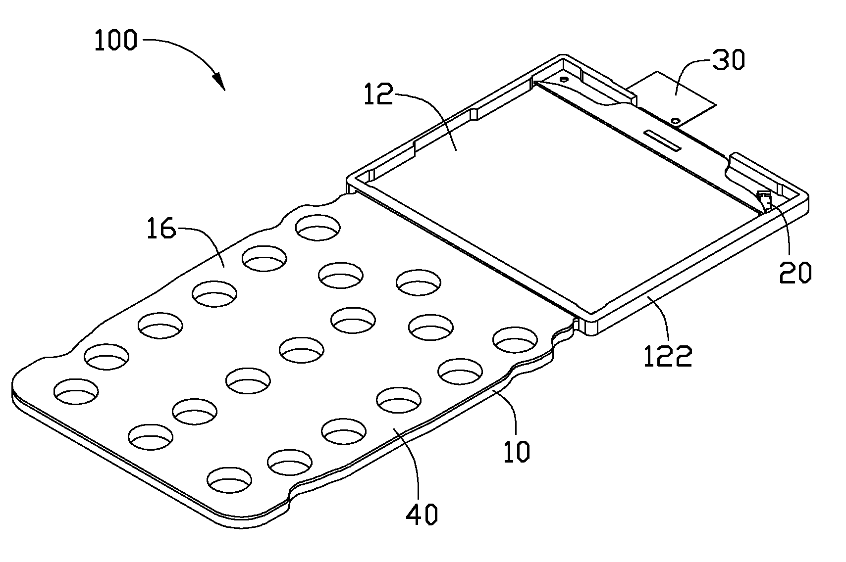
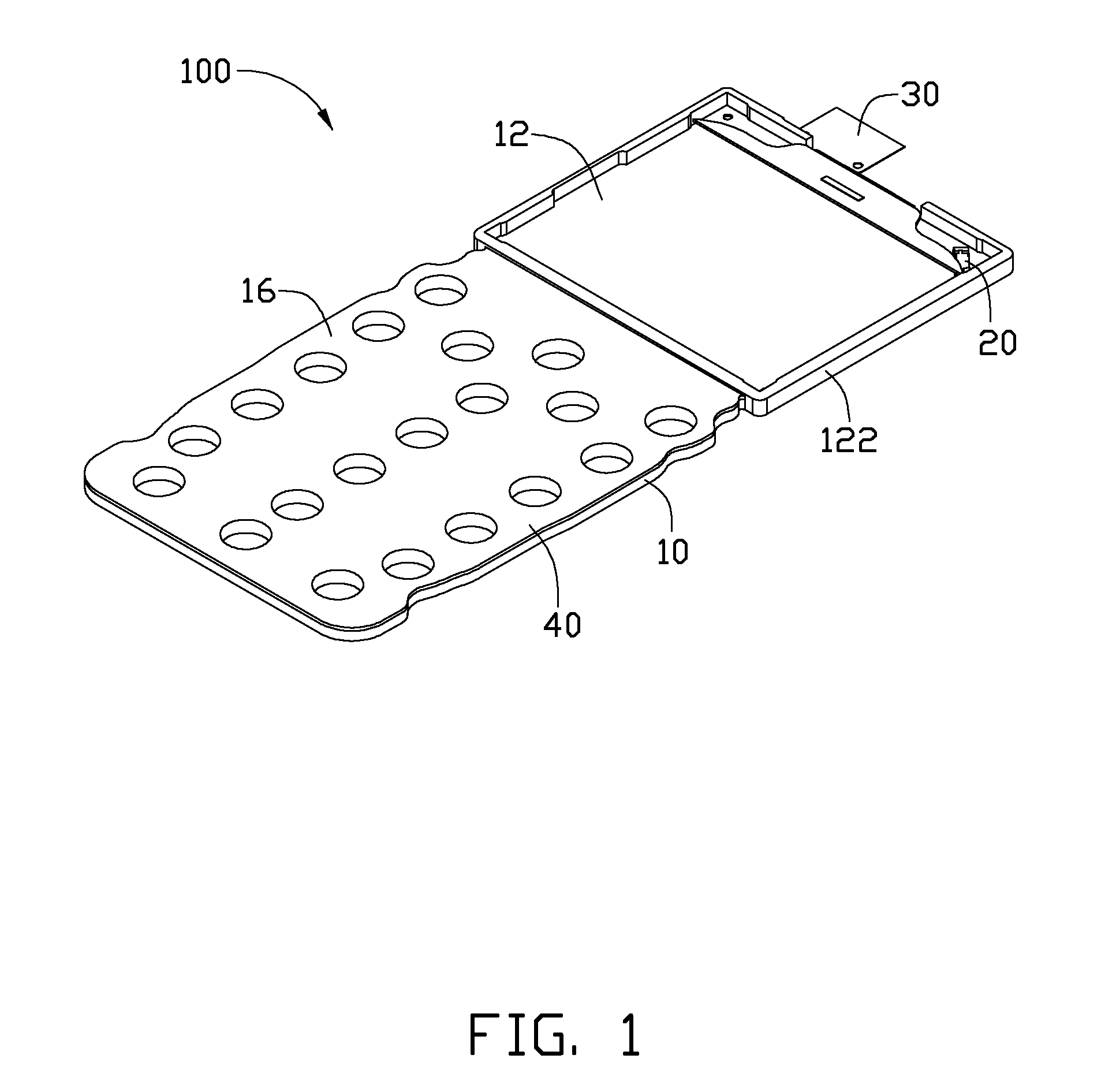
[0011]Referring FIG. 1, a light guide plate assembly 100 includes a light guide plate 10, a light source 20, a flexible printed circuit board 30, and a film 40. The film 40 is attached to one side of the light guide plate 10. The light source 20 is positioned on the board 30 for illuminating the light guide plate 10.

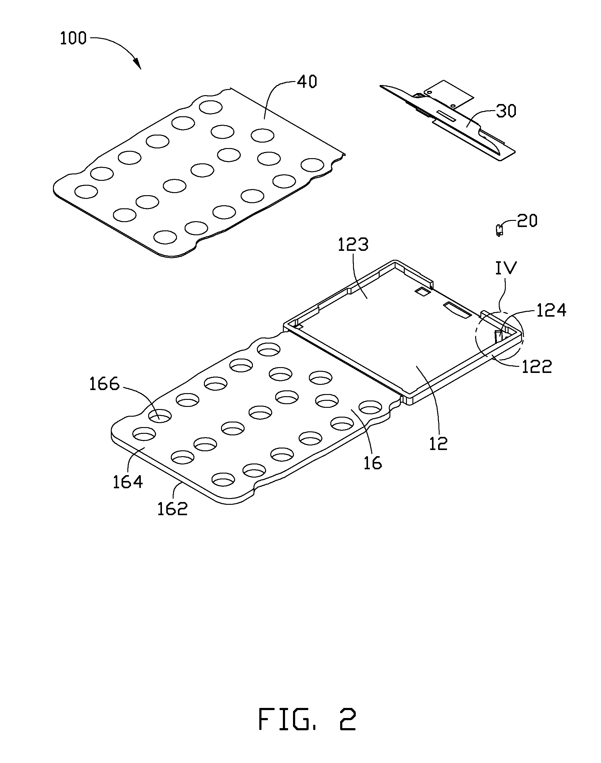
[0012]Referring to FIGS. 2 and 3, the light guide plate 10 is made of a transparent material such as glass or plastic. The plastic material can be any of acrylic, polyvinylchloride resin (PVC), polycarbonate (PC), polystyrene (PS), and polypropylene (PP). The light guide plate 10 includes a first light guide area 12 and a second light guide area 16 integrally formed together. A rectangular frame 122 is positioned on the first light guide area 12, and defines a receiving cavity 123. The receiving cavity 123 is used for accommodating a display module of a portable electronic device.

[0013]The first light guide area 12 is used for illuminating the display module. A corner of...


PUM


Abstract

A light guide plate includes a light source, a first light guide area and a second light guide area. The first light guide area and the second light guide area are formed by a single light guide plate. The first light guide area defines a notch, and the light source is positioned in the notch. A plurality of microdots are provided on one side of the second light guide area, and the microdots uniformly guiding light from the light source to the second light guide area.

Description

BACKGROUND[0001]1. Technical Field[0002]The present disclosure relates to light guide plate assemblies and, particularly, to a light guide plate assembly for a portable electronic device.[0003]2. Description of Related Art[0004]In portable electronic devices, liquid crystal displays (LCDs) and keypads need respective light sources and light guide plates for illumination. Using many light sources and plates may make further miniaturization of devices difficult. In addition, using multiple light sources and light guide plates is costly.[0005]Therefore, there is room for improvement within the art.BRIEF DESCRIPTION OF THE DRAWINGS[0006]Many aspects of the embodiments can be better understood with references to the following drawings. The components in the drawings are not necessarily drawn to scale, the emphasis instead being placed upon clearly illustrating the principles of the present light guide plate assembly. Moreover, in the drawings, like reference numerals designate correspond...

Claims


Application Information

Patent Timeline
Patent Type & Authority Patents(United States)
IPC IPC(8): F21V8/00
CPCG02B6/0033H04M1/22
Inventor TAN, ZHENG-PINGCHEN, KUAN-HUNGWANG, SHI-FENG
Owner SHENZHEN FUTAIHONG PRECISION IND CO LTD
Why Eureka
Try Eureka