Tandem surface light source device

a surface light source and dimming technology, applied in the direction of identification means, lighting and heating apparatus, instruments, etc., can solve the problems of hardly realizing the brightness uniformity over the whole emission face, serious difficulties, and enlarging the emission area, and achieve the effect of presenting a large shining area with ease and being easily enlarged

Inactive Publication Date: 2001-06-05
NITTO JUSHI IND +1
View PDF5 Cites 198 Cited by
  • Summary
  • Abstract
  • Description
  • Claims
  • Application Information

AI Technical Summary

Benefits of technology

An object of the present invention is to provide a surface light source device that is capable of presenting a large shining area with ease as well as capable of securing spaces for arrangement of an increased number of primary light sources with...

Problems solved by technology

Nevertheless conventional surface light source devices as described above have an advantage that thin structure is allowed, they are subject to serious problems against enlarging of emission area.
In particular, increased depth (distance from the incidence end face 2 and distal portion 7) not only requires the primary light source L to have increased power but also leads to difficulty that uniform brightness over the whole emission face is hardly realized.
In general, serious difficulty arises when depth is greater than about 10 inches.
Such arrangement makes it difficult to realize thin structure.
And besides, difference ...

Method used


Image

  • Tandem surface light source device
  • Tandem surface light source device
  • Tandem surface light source device

Examples


first embodiment

Action (behavior of light) of the first embodiment constructed as above described is outlined as follows. For the sake of explanation, the outlines are itemized.

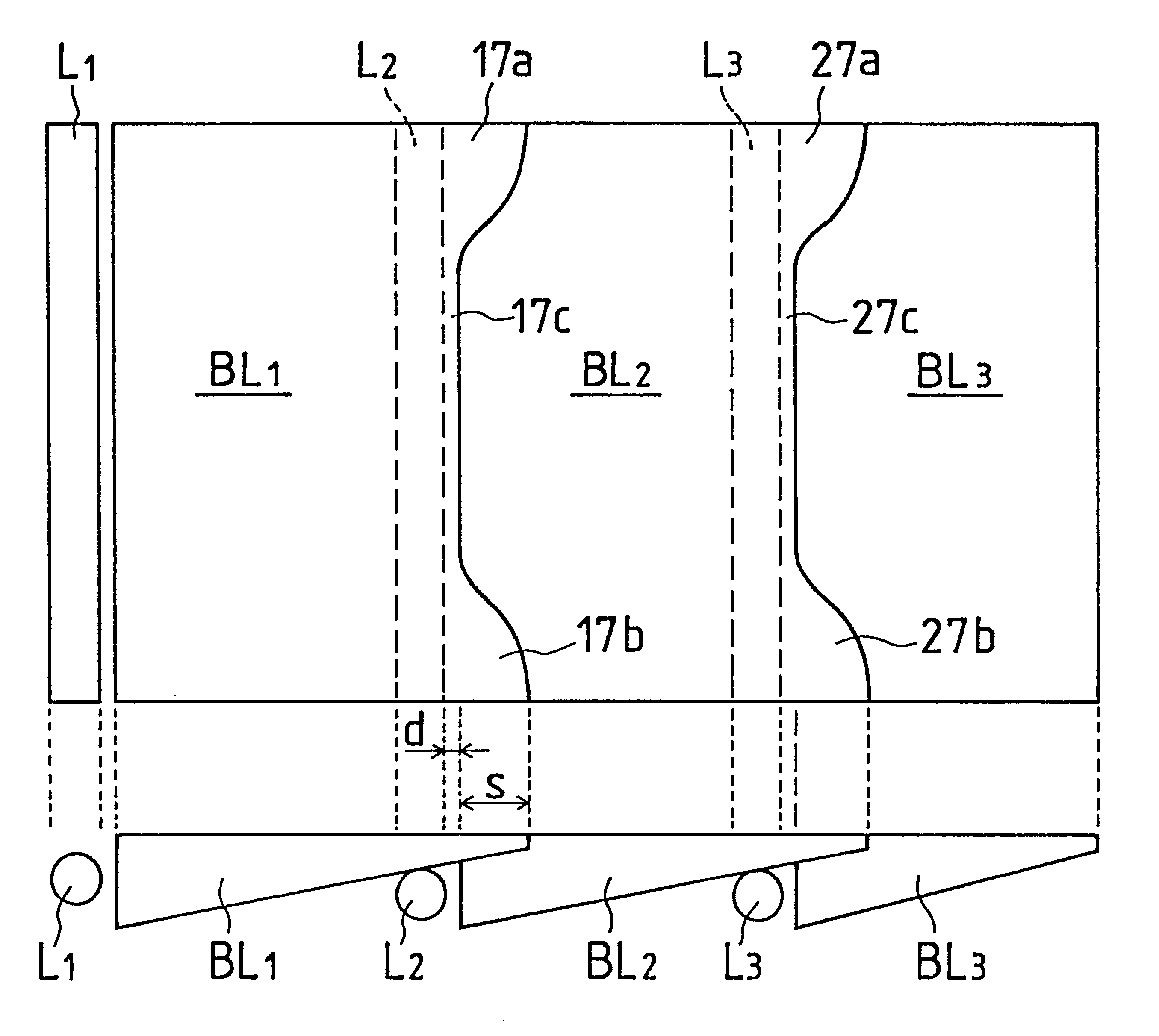
(1) First-step guide plate B L 1; The primary light source L 1 emits light, which is introduced into the guide block L 1 and is guided toward a distal portion 17 at thinner side, with being subject to scattering and reflection. In this process, illumination light is emitted gradually and obliquely forward preferentially from the emission face 15. As mentioned above, the guide block B L 1 is supplied with no direct light from the primary light source B L 1. This prevents excessive brightening from occurring at or around the distal portion 17.

However, effects such as scattering can cause the guide block B L 1 to have an inflow of light that consists of a very small part of light introduced once into the guide block B L 2 and enters into the guide block B L 1 through the abutting faces 22b and 17a.

And, there can be a flow of li...

fifth embodiment

However, a plurality of such guiding-emission mechanisms of tandem type may be arranged side by side. An arrangement of such type is shown in FIG. 7 illustrating an outlined plan view of the fifth embodiment, where elements such as prism sheet, reflection member and housing are eliminated in the illustration.

As shown in the illustration, one guiding-emission mechanism of tandem type is composed of guide blocks B L 1, B L 2, B L 3 and primary light sources L 1, L 2, L 3 supplying primary light to the respective guide blocks while another guiding-emission mechanism of tandem type is composed of guide blocks B L 1', B L 2', B L 3' and primary light sources L 1', L 2', L 3' supplying primary light to the respective guide blocks.

These two guiding-emission mechanisms of tandem type are arranges side by side, thereby providing a tandem surface light source device having an emission area which is enlarged in two dimensions. Each of the mechanisms may be constructed in the same way as the fi...


PUM


Abstract

A set of light guide blocks B L 1~B L 3 provide a tandem arrangement. The light guide block B L 1 is supplied with light from a primary light source L 1. The other primary light sources L 2, L 3 are arranged in recesses formed around distal portions of the light guide blocks B L 1, B L 2, supplying the light guide blocks B L 2, B L 3 with primary light, respectively. Overlap of mutually neighboring light guide blocks gives tang-shaped overlapping portions 17a, 17b, 27a, 27b as well as overlapping bands 17c, 27c, thereby avoiding electrodes at both ends of the primary light sources L 2, L 3 from causing short of brightness. The light guide blocks B L 1~B L 3 may be in the form of unified single guide plate. Primary light sources L 1~L 3 may have a shape such that electrode sections of both ends are curved. A compact surface light source device with a large emission area is provided.

Description

The present invention relates to a surface light source device provided with a primary light source emitting light which is converted into an illumination flux having a large cross section to be outputted, more specifically, relates to a tandem light source device comprising a plurality of plate-like light guide blocks disposed tandem. Tandem surface light source devices in accordance with the present invention are applied with advantage in particular to backlighting for LCD (liquid crystal display) having a large display screen.Surface light source devices which employ guide plates made of light scattering and guiding materials or transparent light guiding materials have been proposed and broadly applied to backlighting for LCD and other uses. Conventional surface light source devices are generally classified into a type featured by light supply from a side of light guiding means and another featured by light supply from behind light guiding means. The former is called surface ligh...

Claims


Application Information

Patent Timeline
IPC IPC(8): F21V8/00G09F9/00F21Y103/00G02B6/00G02F1/1335G02F1/13357
CPCG02B6/0068G02B6/008G02B6/0021G02B6/0046G02B6/0053G02B6/0071G02F1/1335
Inventor HIGUCHI, EIZABUROISHIKAWA, TSUYOSHIHORIBE, AKIHIRO
Owner NITTO JUSHI IND
Why Eureka
Try Eureka