Image encoding device and image encoding method

a technology of image encoding and encoding method, which is applied in the direction of instruments, electrical appliances, computing, etc., can solve the problems of increasing the image quality of the entire image, and achieve the effect of reducing the image quality deterioration

Inactive Publication Date: 2013-07-09
SONY CORP
View PDF13 Cites 0 Cited by
  • Summary
  • Abstract
  • Description
  • Claims
  • Application Information

AI Technical Summary

Benefits of technology

[0010]In the case of using encoded streams of such a long GOP configuration to perform editing processing or the like, various types of processing, e.g., color collection, cut editing, or the like is performed as to image data obtained by decoding the encoded streams. Also, the image data after editing is encoded again to generate encoded streams. Thus, in the event of encoding and decoding being repeated, when the picture type differs from the last encoding, deterioration in image quality may become marked as compared to a case where the picture types are the same. For example, in the event of performing encoding so as to suppress deterioration in image quality of a reference picture by assigning great code amount to a reference picture to be referred from another picture, deterioration in image quality of the entire image can be reduced. Thus, when improving subjective image quality by providing image quality difference between a reference picture and a non-reference picture, in the event of a non-reference picture of which the image quality is inferior to the image quality of a reference picture being set to a reference picture at the next encoding, deterioration in image quality of the entire image increases.
[0011]Accordingly, it has been found to be desirable to provide an image encoding device and an image encoding method whereby deterioration in image quality can be reduced even when encoding and decoding of image data is repeated by employing a GOP configuration including reference pictures and non-reference pictures in a predetermined order.
[0015]With the quantization information distinguishing unit, calculation of a DCT coefficient is performed with the image of each frame of image data as an I picture, and quantization information that minimizes the summation of remainders, in increments of pictures, when performing division of the DCT coefficient using quantization information is distinguished to be the quantization information used at the time of performing the last encoding. Here, the quantization information to be used for distinction is quantization information of a range with the quantization information set at the code amount control unit as a reference, and accordingly, distinction does not have to be performed using all of the quantization information, and distinction of quantization information used at the time of performing the last encoding is facilitated.
[0016]With the picture-type setting unit, setting of a picture type is performed in increments of GOPs as to image data, and when the set picture type, and the picture type of which the quantization information has been distinguished at the quantization information distinguishing unit, differ, the picture types are matched by controlling the setting of the subsequent picture type. For example, the picture-type setting unit performs, at the time of the I picture distinguished at the quantization information distinguishing unit of which the phase advances as compared to the I picture to be set to the image data, adjustment of the length of GOP by reducing the number of pictures earlier than the I picture by the number of advancing pictures to match a picture type to be set to the image data, and a picture type at the time of performing the last encoding. Also, the picture-type setting unit performs, at the time of the I picture distinguished at the quantization information distinguishing unit of which the phase is lagging as compared to the I picture to be set to the image data, adjustment of the length of GOP by reducing the number of pictures of the next single or plurality of GOP to match the picture types of a reference picture and a non-reference picture to be set to the image data, and a picture type at the time of performing the last encoding. Such setting of a picture type is performed at the picture-type setting unit, and accordingly, the same picture type as that of the last encoding may be set to the image data.
[0018]Further, when a third encoding unit is provided to calculate a generated code amount by performing encoding for each of the quantization information with the image of each frame of the image data as an I picture using a plurality of different quantization information, the code amount control unit performs prediction of quantization information that realizes a target generated code amount, and a generated code amount at the time of using this quantization information based on the generated code amount calculated at the first encoding unit, corrects the predicted generated code amount according to the generated code amount calculated at the third encoding unit, and performs setting of quantization information such that the generated code amount after correction realizes the target generated code amount. Thus, the quantization information realizing a target generated code amount can be distinguished with precision, and quantization information to be used for distinction of quantization information used at the time of performing the last encoding can accurately be selected.
[0020]Thus, deterioration in image quality can be reduced even when performing encoding and decoding of image data by employing a GOP configuration including a reference picture and a non-reference picture in a predetermined order.

Problems solved by technology

Thus, when improving subjective image quality by providing image quality difference between a reference picture and a non-reference picture, in the event of a non-reference picture of which the image quality is inferior to the image quality of a reference picture being set to a reference picture at the next encoding, deterioration in image quality of the entire image increases.

Method used


Image

  • Image encoding device and image encoding method
  • Image encoding device and image encoding method
  • Image encoding device and image encoding method

Examples


first embodiment

2. Operation of First Embodiment

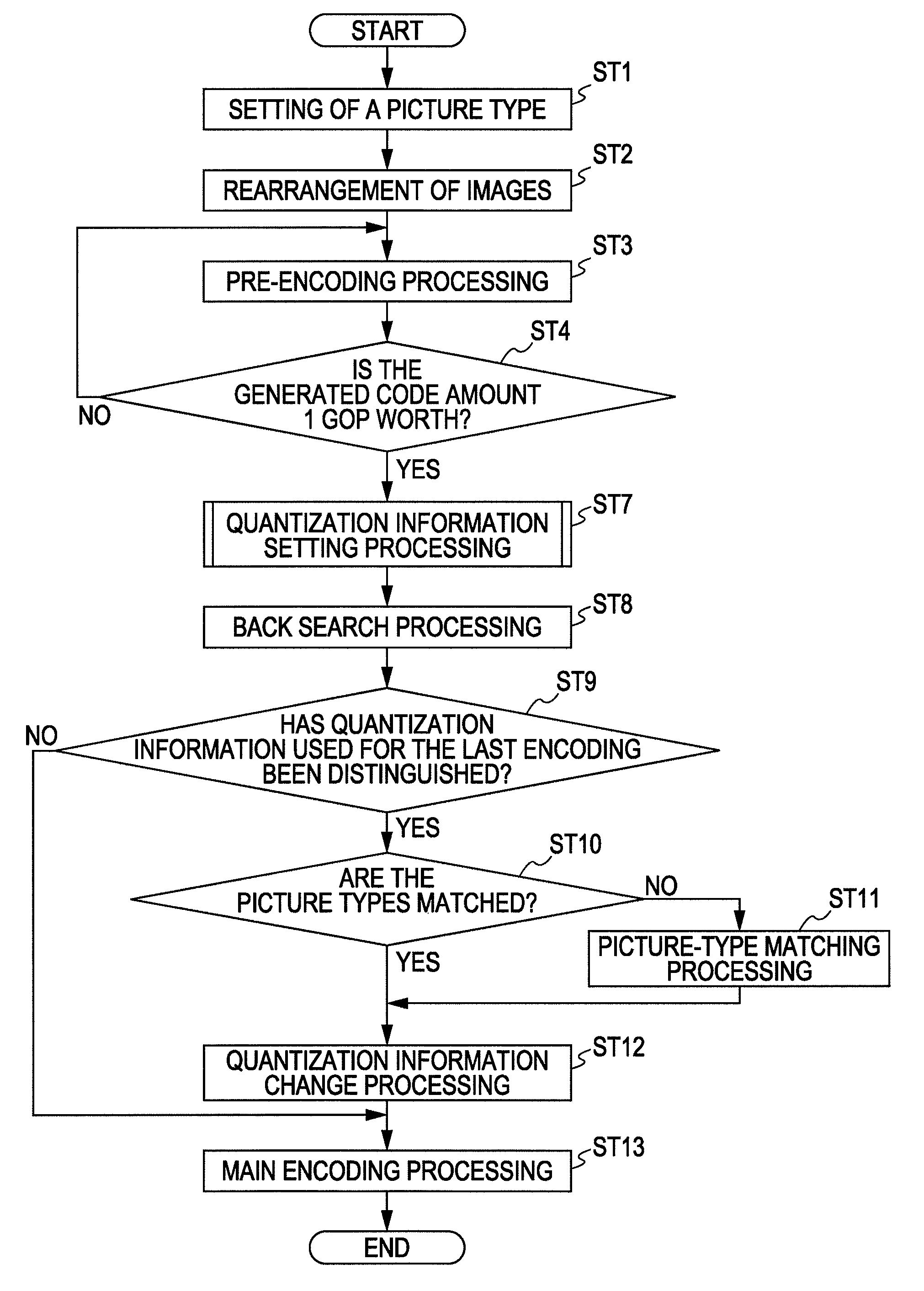
[0079]Next, the operation of the first embodiment will be described. FIG. 5 is a flowchart illustrating the operation of the first embodiment. Note that FIG. 5 illustrates processing of 1 GOP.

[0080]In step ST1, the image encoding device 10 performs setting of a picture type. The image encoding device 10 sets a picture type to each frame of the image data at the picture-type setting unit 11 in accordance with a GOP (Group of Picture) configuration, and proceeds to step ST2.

[0081]In step ST2, the image encoding device 10 performs rearrangement of images. The image encoding device 10 rearranges the image data at the image rearrangement processing unit 12 from the display sequence to the encoding sequence based on the picture type set at the picture-type setting unit 11, and proceeds to step ST3.

[0082]In step ST3, the image encoding device 10 performs pre-encoding processing. The image encoding device 10 performs encoding of the image data at the pre-enco...

second embodiment

4. Operation of Second Embodiment

[0138]Next, the operation of the second embodiment will be described. FIG. 14 is a flowchart illustrating the operation of the second embodiment. Note that the processing corresponding to the operation of the image encoding device illustrated in FIG. 5 will be denoted with the same step number.

[0139]In step ST1, the image encoding device 10a performs setting of a picture type, and proceeds to step ST2. In step ST2, the image encoding device 10a performs rearrangement of images. In step ST3, the image encoding device 10a performs the pre-encoding processing. In step ST4, the image encoding device 10a distinguishes whether or not the generated code amount calculated in the pre-encoding processing has reached 1 GOP worth. In the event that the generated code amount calculated at the pre-encoding unit 20 has reached 1 GOP worth, the image encoding device 10a proceeds to step ST7, and in the event that the generated code amount has not reached 1 GOP worth...


PUM


Abstract

An image encoding device includes: a first encoding unit for calculating a generated code amount by encoding image data for each GOP (Group of Picture); a code amount control unit for setting quantization information for realizing a target generated code amount based on the generated code amount; a quantization information distinguishing unit for calculating a DCT (Discrete Cosine Transform) coefficient, and distinguishing quantization information that minimizes the summation for each picture of remainders when performing division of the DCT coefficient, as quantization information used for performing the last encoding; a picture-type setting unit for setting a picture type to the image data for each GOP, and when this set picture type differs from the picture type of the distinguished quantization information, matching the picture types by controlling the settings of the subsequent picture types; and a second encoding unit for encoding the image data based on the set picture type.

Description

BACKGROUND OF THE INVENTION[0001]1. Field of the Invention[0002]The present invention relates to an image encoding device, and an image encoding method, and more specifically, it relates to an image encoding device, and an image encoding method, whereby deterioration in image quality can be reduced even when repeating encoding and decoding of an image by employing a long GOP configuration.[0003]2. Description of the Related Art[0004]Hitherto, with an image encoding method such as MPEG2 (Moving Picture Experts Group 2) or the like, it is a great problem to maintain subjective image quality to ideally distribute a code amount.[0005]For example, an ideal code amount distribution of a still image is a state in which distortion is uniformly encoded (with a fixed quantized scale). When reaching a code amount whereby this distortion becomes great, subjective image quality can be enhanced by biasing the distortion toward a high-frequency component or complicated portion.[0006]Now, for examp...

Claims


Application Information

Patent Timeline
Patent Type & Authority Patents(United States)
IPC IPC(8): G06K9/46G06K9/36H04N19/50H04N19/124H04N19/134H04N19/136H04N19/146H04N19/177H04N19/40H04N19/503H04N19/593H04N19/60H04N19/61H04N19/625H04N19/91
CPCH04N19/159H04N19/172H04N19/149H04N19/61H04N19/40H04N19/114H04N19/126H04N19/177H04N19/194H04N19/107
Inventor KOYABU, KYOHEIFUCHIE, TAKAAKI
Owner SONY CORP
Why Eureka
Try Eureka