System and method for optimizing machining simulation

a technology of simulation and optimization, applied in the field of machining simulation, can solve the problems of small discrepancies between the actual the desired final shape of the workpiece, and the inability of the g-code generated by the computer aided manufacturing system to produce an exact replication of the desired final shape,

Active Publication Date: 2013-07-09
MITSUBISHI ELECTRIC RES LAB INC
View PDF11 Cites 14 Cited by
  • Summary
  • Abstract
  • Description
  • Claims
  • Application Information

AI Technical Summary

Problems solved by technology

The G-Codes generated by the computer aided manufacturing system can fail to produce an exact replication of the desired final shape.
In addition, the movement of the tool is governed by motors of the NC machining system, which have limited speeds, ranges of motion, and abilities to accelerate and decelerate, so that the actual tool motions sometimes do not exactly follow the NC machining instructions.
Discrepancies between the actual final shape of the workpiece and the desired final shape of the workpiece can be very small, and difficult to see.
In some situations, these discrepancies result in undesirable gouges or nicks in the surface of the final shape of the workpiece with sizes on the order of a few micrometers in depth and width, and tens of micrometers in length.
However, this manual testing is time consuming and expensive.
Unfortunately, the aforementioned methods of determining the subset of the distance fields of the cell can result in poor simulator performance, because a number of distance fields of the subset found by those methods can represent swept volumes that enter the cell, but do not form a portion of the workpiece boundary.

Method used


Image

  • System and method for optimizing machining simulation
  • System and method for optimizing machining simulation
  • System and method for optimizing machining simulation

Examples


Embodiment Construction

[0054]System Overview

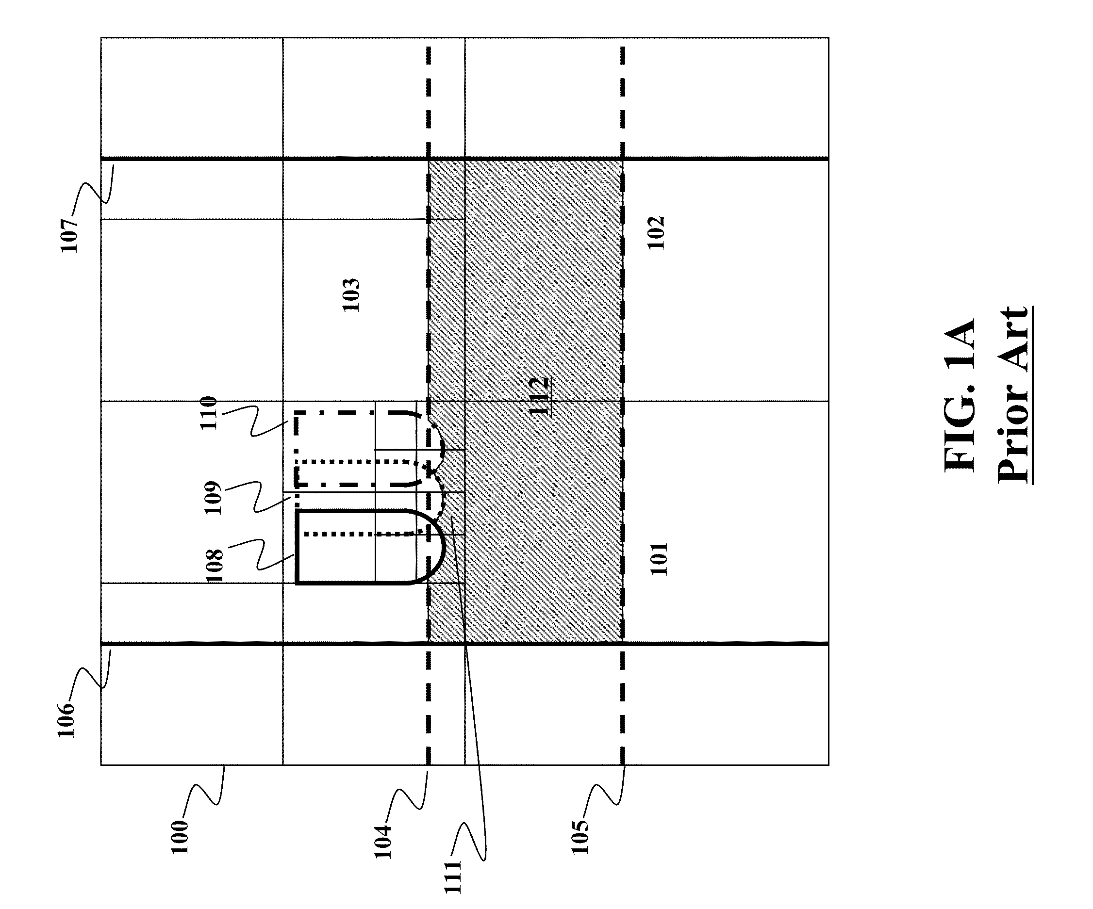
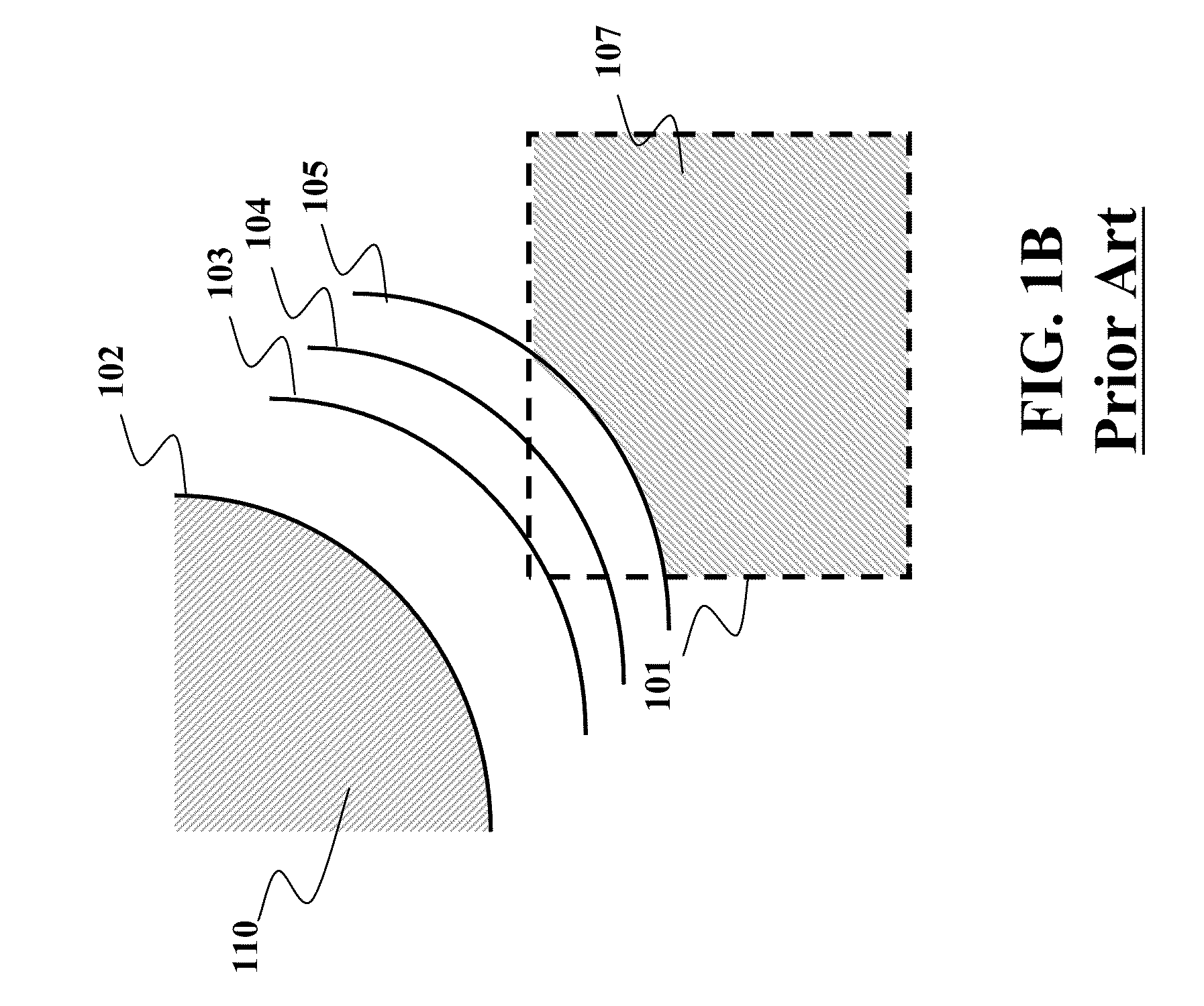
[0055]FIG. 4A illustrates a problem addressed by embodiments of the invention. Within a cell 400, a boundary 402 defines an original surface of a workpiece 401 at the start of a simulation of a milling of the workpiece. During the simulation, boundaries of three swept volumes 403, 404, and 405 intersect with the cell. Accordingly, the swept volumes are removed from a volume of the workpiece represented by the cell. A composite surface of the workpiece 406 enclosing an interior 407 of the workpiece is formed by the boundary 402 and the boundary 405.

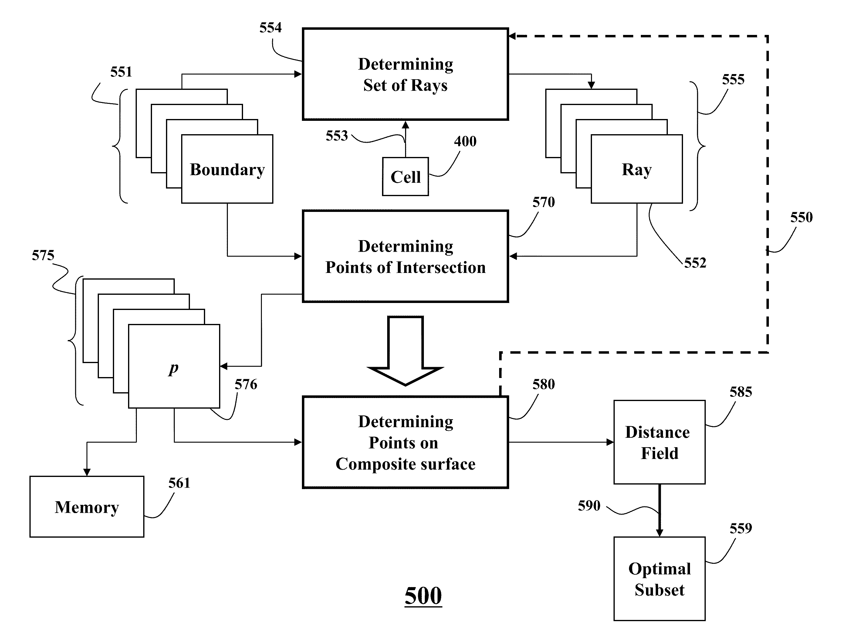
[0056]In various embodiments of the invention, the workpiece and the swept volumes are represented with distance fields. The cell is associated 450 with a subset 551 of distance fields that initially includes the distance fields representing the boundaries 402-405 intersecting with the cell. Embodiments of the invention optimize 500 the subset forming an optimal subset 559 that includes the distance fields representing...


PUM


Abstract

Embodiments of the invention disclose a method for optimizing a simulation of a machining of a workpiece performed by removing a set of swept volumes from a volume of the workpiece, wherein the volume is partitioned into a set of cells, comprising the steps of: associating with each cell a subset of distance fields representing a subset of swept volumes intersecting with the cell, wherein at least part of the subset of swept volumes forms a composite surface of the cell; subjecting the cell with a set of rays incident to the cell from at least one direction; and selecting a distance field of the subset of distance fields into an optimal subset associated with the cell, wherein a boundary of the swept volume represented by the distance field intersects with at least one ray at a point of intersection lying on the composite surface.

Description

FIELD OF THE INVENTION[0001]The invention relates generally to machining simulation, and more particularly to determining an optimal subset of distance fields to optimize a simulation of a machining process.BACKGROUND OF THE INVENTION[0002]Numerically Controlled Milling[0003]Simulating a process of numerically controlled (NC) machining (e.g. milling or turning) is of fundamental importance in computer aided design (CAD) and computer aided manufacturing (CAM). During the simulation, a computer model of a workpiece is edited with a computer representation of a tool, e.g., an NC milling tool, and a set of motions of the tool, which simulate the machining process.[0004]The simulation visualizes the model of the workpiece and the representation of the tool in order to detect potential collisions between parts, such as the workpiece and the tool holder, and to verify a final shape of the workpiece.[0005]The final shape of the workpiece is affected by the selection of the tool and the moti...

Claims


Application Information

Patent Timeline
Patent Type & Authority Patents(United States)
IPC IPC(8): G06F19/00G06F7/60G06F17/50G06F17/10G06T17/00G06G7/48
CPCG05B19/40937G06T17/10G06F17/5009G06T17/00G05B2219/35009G05B2219/35148G05B2219/35287G06F30/20Y02P90/02
Inventor SULLIVAN, ALANYERAZUNIS, WILLIAM S.
Owner MITSUBISHI ELECTRIC RES LAB INC
Why Eureka
Try Eureka