
Metal gasket

a metal gasket and gasket body technology, applied in the direction of sleeve/socket joints, cable terminations, mechanical devices, etc., can solve the problems of large force being basically required to deform the gasket, the bolt cannot be rotated in a timely fashion, and the bolt is rarely rotated, so as to reduce the total tightening load and reduce the deformation amount. , the effect of low hardness

Active Publication Date: 2013-07-16
TOHOKU UNIV +1
View PDF24 Cites 3 Cited by
  • Summary
  • Abstract
  • Description
  • Claims
  • Application Information

AI Technical Summary

Benefits of technology

The metal gasket in this patent has a simple inner ring design that improves sealing and adhesion, while also allowing for a lower total tightening load and easier maneuvering by hand. Additionally, the design prevents damage to the flange surface and protects against leakage.

Problems solved by technology

On the other hand, in the state in which a bolt is attained to be tightened in a groove, the bolt cannot be rotated in a timely fashion or the bolt is rotated hardly.
On the other hand, in the case of a gasket made of metal in an O-ring shape, a large force is basically required to deform the gasket, whereby it is hard to find a change of a moment when a bolt is tightened to a groove.
Therefore, it is hard to manage a tightening of a bolt by a manual work unfortunately.
Even in the case of a metal hollow O-ring and a metal C-ring provided with a spring, it is hard to find a change of a moment when a bolt is tightened, whereby it is hard to manage a tightening of a bolt by a manual work unfortunately.
However, in the case in which a thickness of a spring is modified, a reaction force or a stress of a seal face is degraded, whereby a sealing property is also degraded unfortunately.
However, even by the above ideas for an improvement, a sealing property cannot be displayed to a satisfactory extent by a smaller tightening force.
Moreover, in the case in which a shape that causes a concentration of stress on a seal face is adopted like the Patent documents 1 and 2 in particular, a flaw may be remained on a face of a flange on the other side due to the shape of the seal face, whereby a problem occurs in a reuse of a flange in some cases.
Moreover, since a portion of a concentration of stress is in a convex shape, the portion may be easily damaged, whereby a care and an attention must be paid in handling unfortunately in particular.

Method used


Image

  • Metal gasket
  • Metal gasket
  • Metal gasket

Examples


Embodiment Construction

[0032]An embodiment (example) of a metal gasket in accordance with the present invention will be described below in detail with reference to the drawings.

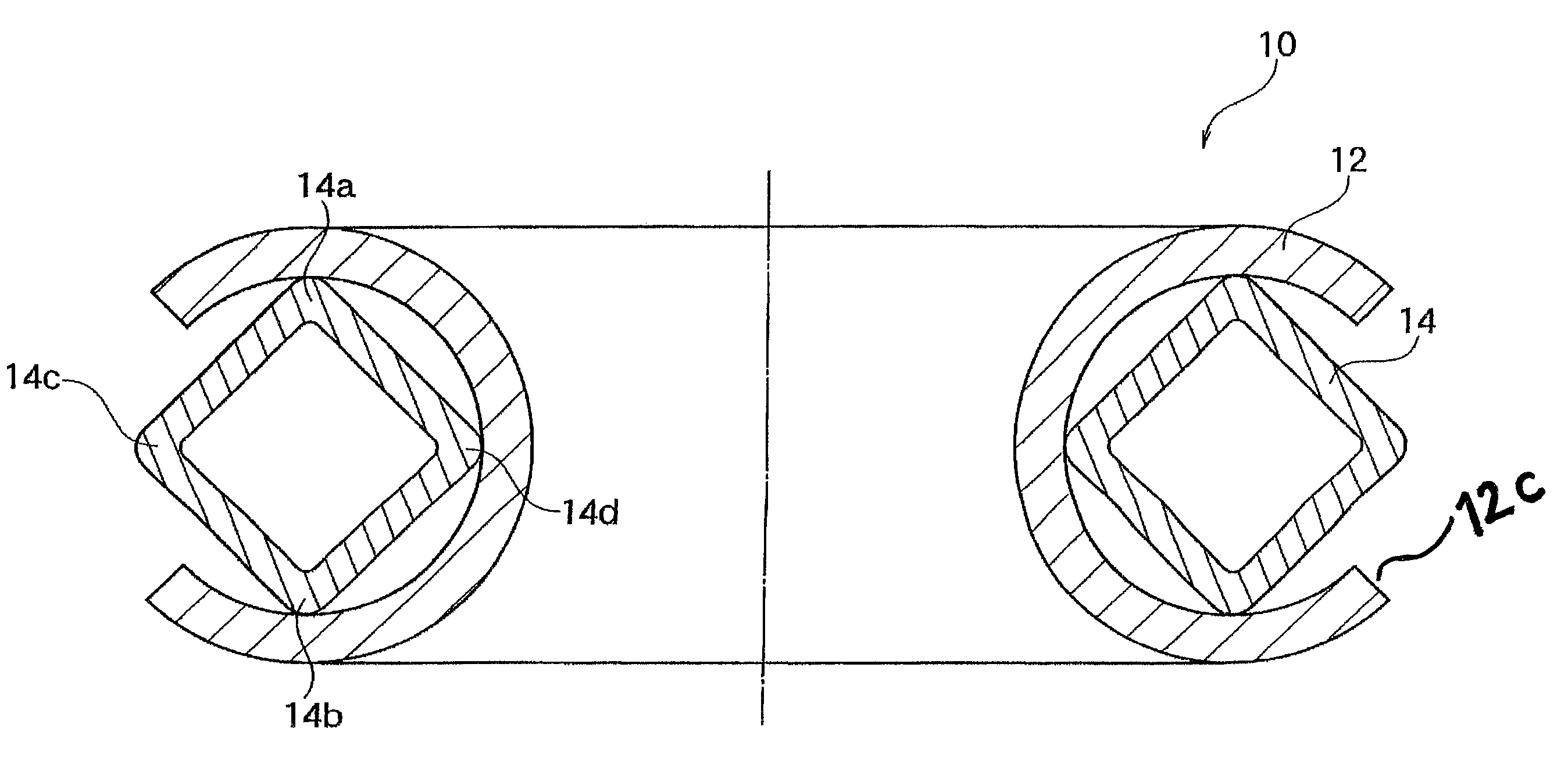
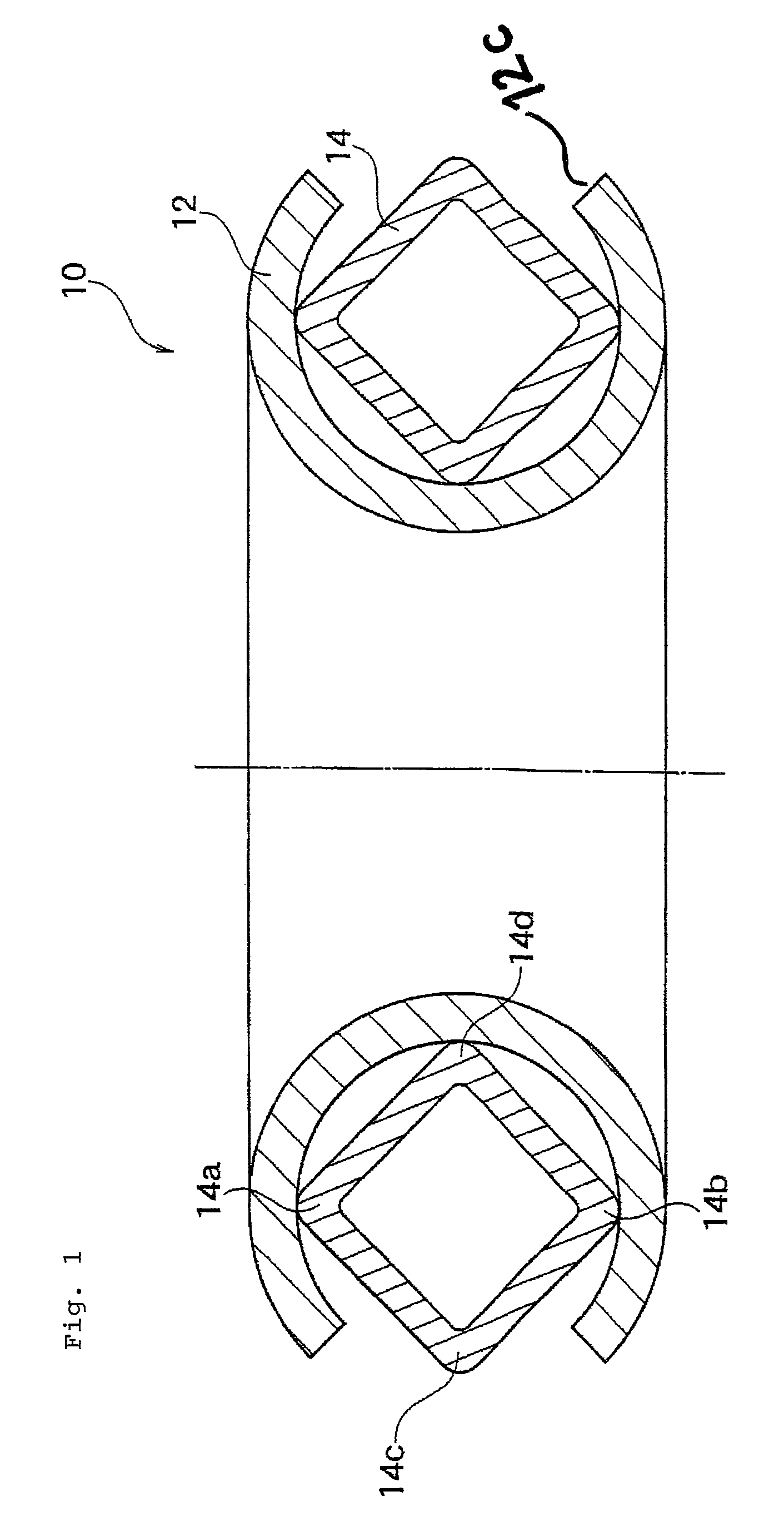
[0033]FIG. 1 is a cross-sectional view showing a metal gasket in accordance with a presently preferred embodiment of the present invention.

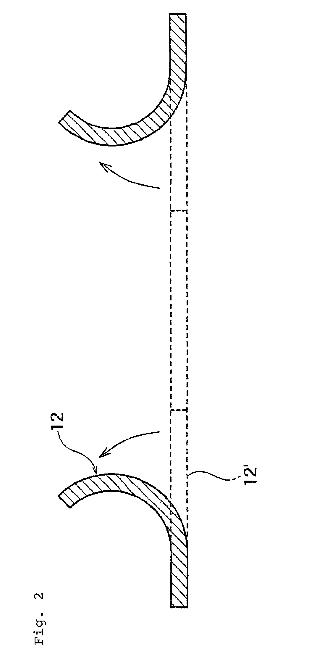
[0034]As shown in FIG. 1, a metal gasket 10 is configured by an outer ring 12 that is formed in a generally C-shaped cross-section and a hollow inner ring 14 in a generally quadrangular shape of a cross section.

[0035]It is preferable that a metal that configures the inner ring 14 is harder than a metal that configures the outer ring 12. It is preferable that the outer ring 12 is made of aluminum that is a so-called soft metal, and the inner ring 14 is made of a metal that is harder than aluminum, such as a stainless steel.

[0036]In other words, for the metal gasket 10 in accordance with the present embodiment, a degree of hardness of the outer ring 12 that is disposed on a seal face is lower than...


PUM


Abstract

A metal gasket includes an outer ring that is formed in a substantially C-shaped cross-section having an opening in a circumferential direction and an inner ring that is disposed inside the outer ring, wherein the inner ring is configured in a polygonal shape of a cross section, and a pair of corner portions opposing to each other in the inner ring are disposed on inner circumferential faces on the both sides of the opening in the outer ring.

Description

TECHNICAL FIELD[0001]The present invention relates to a metal gasket that is used as a seal member under the severe conditions such as a high temperature, a high pressure, and a vacuum for a wide variety of pipe arrangements, machinery, and equipment in the fields of a nuclear power, a semiconductor and so on. More specifically, the present invention relates to a metal gasket provided with an excellent sealing property by a small tightening force.BACKGROUND ART[0002]For an application that requires a higher sealing property that does not allow a permeation leakage like a high vacuum application and a heat resistance property to a baking processing for degassing or the like, a metal gasket made of a soft metal material provided with the excellent sealing and heat resistance properties is used in general rather than a material made of a rubber or an elastomer.[0003]In order to ensure a stable sealing property by using a metal gasket as described above, a tightening force must be extre...

Claims


Application Information

Patent Timeline
Patent Type & Authority Patents(United States)
IPC IPC(8): F16L21/05F16J15/02
CPCF16J15/0887F16L23/20F16J15/0893
Inventor OHMISHIRAI, YASUYUKISATONOGUCHI, MASAYUKIYOSHIDA, TSUTOMUMURAMATSU, AKIRAKUMAKI, SATOSHIKUWAMURA, YUKI
Owner TOHOKU UNIV
Learn More