Magnetic recording transducer having side shields

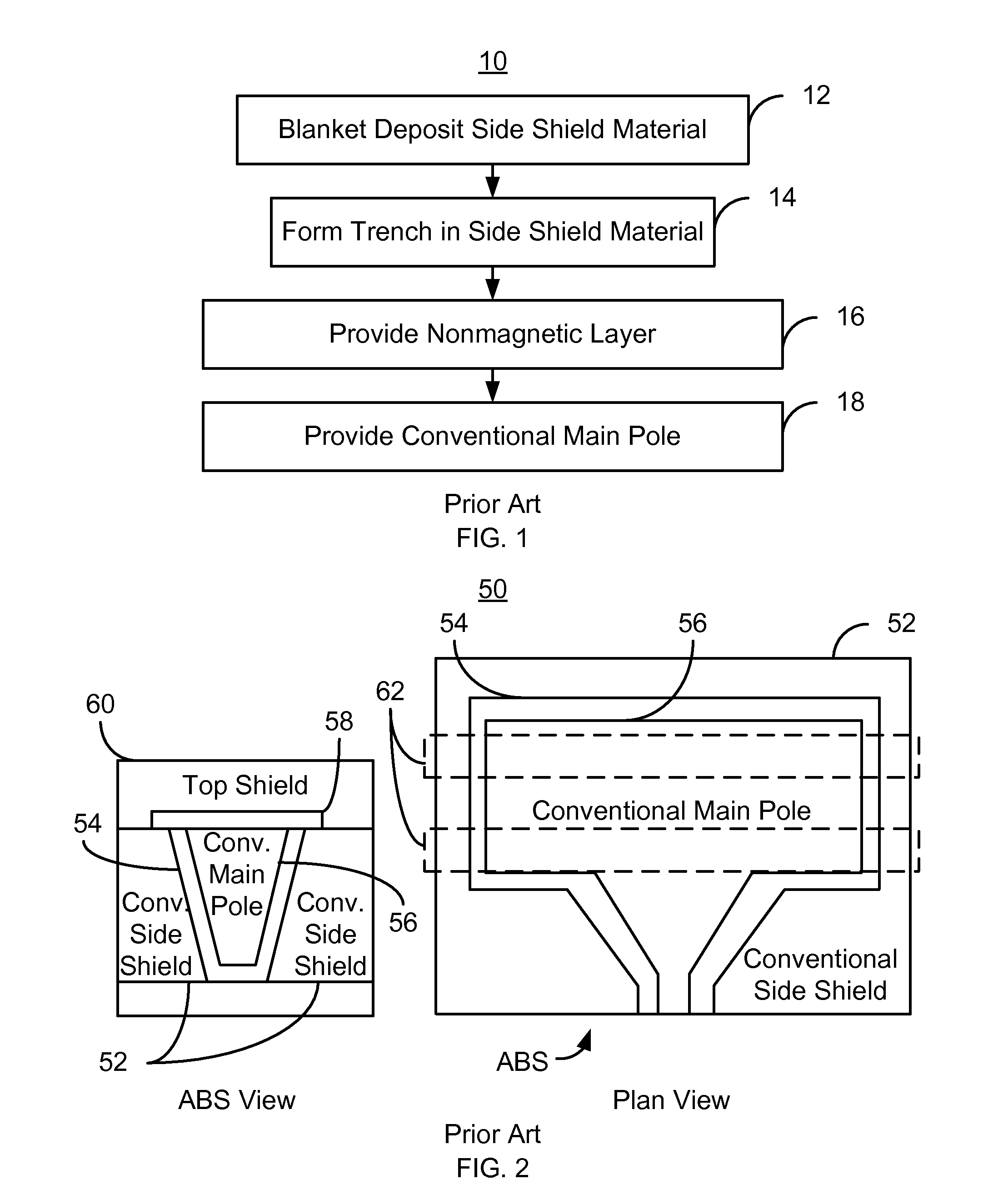
a technology of magnetic recording transducer and side shield, which is applied in the direction of magnetic recording head, data recording, instruments, etc., can solve the problems of difficult control of the nife rie performed in step b>14/b>, difficulty in separate control of the geometry of the conventional side shield, and difficulty in forming a trench having the desired reverse angle and other features

Active Publication Date: 2013-07-16
WESTERN DIGITAL TECH INC
View PDF74 Cites 151 Cited by
  • Summary
  • Abstract
  • Description
  • Claims
  • Application Information

AI Technical Summary

Problems solved by technology

The NiFe RIE performed in step 14 may be difficult to control.
In particular, forming a trench having the desired reverse angle and other features may be problematic.
As a result, it may be difficult to separately control the geometry of the conventional side shield 52 and the geometry of the conventional main pole 56.
As a result, performance of the conventional side shield 52 may suffer.

Method used


Image

  • Magnetic recording transducer having side shields
  • Magnetic recording transducer having side shields
  • Magnetic recording transducer having side shields

Examples


Embodiment Construction

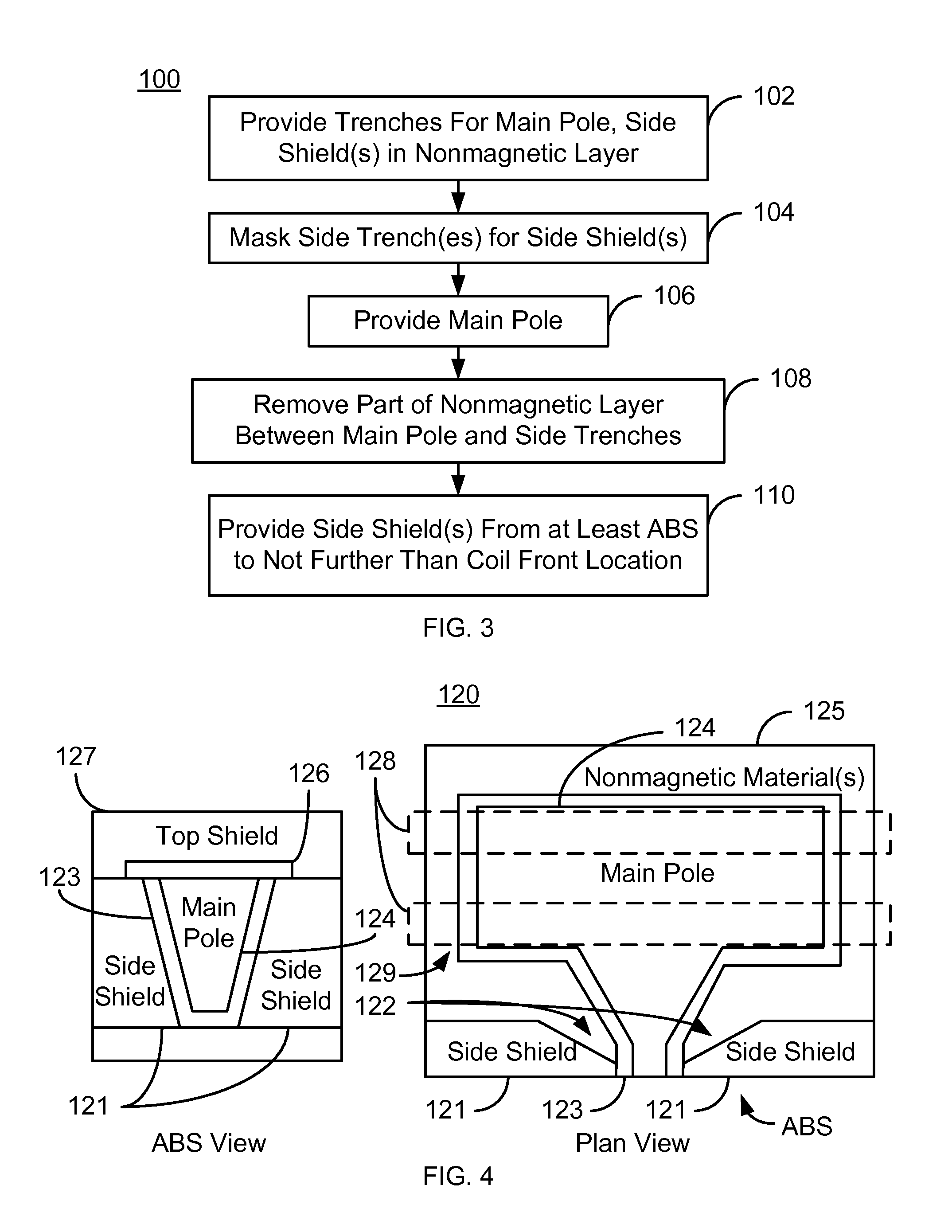
[0016]FIG. 3 is an exemplary embodiment of a method 100 for providing magnetic recording transducer having side shields. For simplicity, some steps may be omitted. The method 100 is also described in the context of providing a single recording transducer. However, the method 100 may be used to fabricate multiple transducers at substantially the same time. The method 100 is also described in the context of particular layers. A particular layer may include multiple materials and / or multiple sublayers. The method 100 also may start after formation of other portions of the magnetic recording transducer. For example, the method 100 commences after formation of an underlayer and a nonmagnetic layer on the underlayer. The underlayer is nonmagnetic and may be an RIE stop layer. In one embodiment, the nonmagnetic layer is an insulator, such as aluminum oxide.

[0017]Trenches are provided in the nonmagnetic layer, via step 102. A first, central trench corresponds to the main pole that is to be ...


PUM

PropertyMeasurementUnit
lengthaaaaaaaaaa
lengthaaaaaaaaaa
nonmagneticaaaaaaaaaa

Abstract

A magnetic recording transducer includes a main pole including a nose portion, the nose portion terminating at an air-bearing surface (ABS). The magnetic recording transducer further includes at least one coil having a coil front distal from the ABS, and at least one side shield, the at least one side shield extending from at the ABS to not further than the coil front.

Description

CROSS REFERENCE TO RELATED APPLICATIONS[0001]This application is a divisional of U.S. patent application Ser. No. 12 / 199,624, filed on Aug. 27, 2008, which is hereby incorporated by reference in its entirety.BACKGROUND[0002]Side shields, as well as top shields may be desired in conventional magnetic recording transducers, particular perpendicular magnetic recording (PMR) transducers. Side shields in combination with top shields that surround the sides and top of the main PMR pole are termed wrap-around shields. FIG. 1 depicts a conventional method 10 for fabricating such a conventional PMR transducer having a wrap-around shield. The method 10 allows fabrication of the side shields without requiring the main pole to be trimmed.[0003]The conventional method 10 commences by blanket depositing a magnetic material used for the conventional side shield, via step 12. Step 12 includes plating a NiFe layer. A trench for the conventional main pole is formed in the NiFe layer, via step 14. The...

Claims


Application Information

Patent Timeline
Patent Type & Authority Patents(United States)
IPC IPC(8): G11B5/127
CPCG11B5/1278G11B5/3116G11B5/315G11B5/3163Y10T29/49044Y10T29/49048Y10T29/49046Y10T29/49052Y10T29/49043
Inventor TRAN, UTBAI, ZHIGANGLIN, KEVIN K.
Owner WESTERN DIGITAL TECH INC
Why Eureka
Try Eureka