
Detecting constrained motion of a component in a computer system

a computer system and component technology, applied in the direction of hydrodynamic testing, instruments, nuclear elements, etc., can solve the problems of computer system aging, disk drives potentially more sensitive to vibration, isolation and damping methods may lose their effectiveness,

Active Publication Date: 2013-07-16
ORACLE INT CORP
View PDF5 Cites 0 Cited by
  • Summary
  • Abstract
  • Description
  • Claims
  • Application Information

AI Technical Summary

Benefits of technology

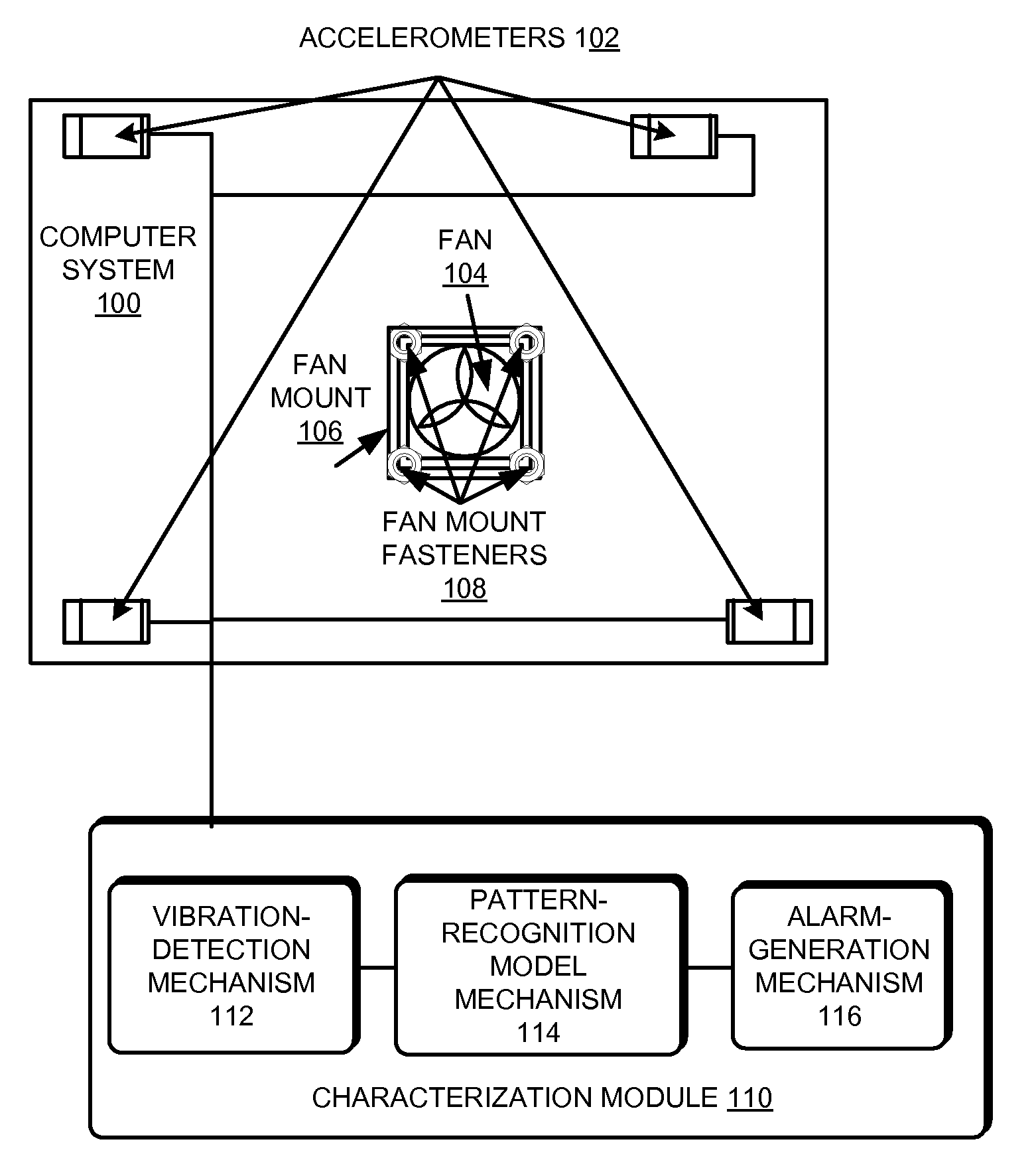
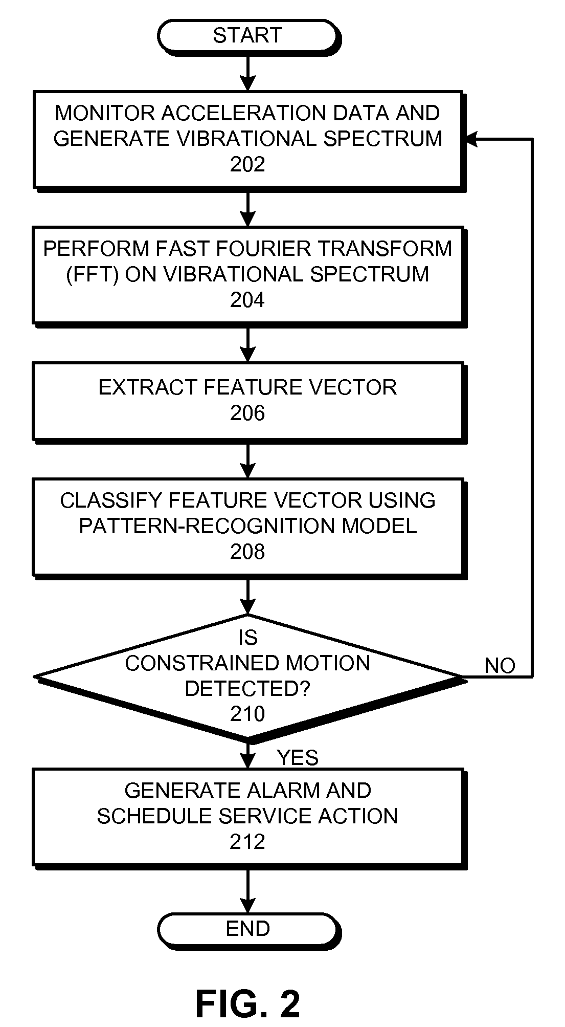
The present invention provides a system to detect constrained motion in computer components. The system monitors the vibrations of the computer system and analyzes them using a pattern-recognition model to identify when there is a likelihood of constrained motion, such as rattling, in components like disk drives, fans, and fans trays. This analysis can be done by analyzing the vibrational spectrum of the computer system or extracting features from it. The system can also generate a request for service action based on the detection of constrained motion. Overall, this invention allows for timely detection and response to potential issues in computer systems.

Problems solved by technology

Unfortunately, smaller track sizes and tighter tolerances make such disk drives potentially more sensitive to vibrations during operation of the computer system.
Additionally, manufacturers often use isolation and damping methods to control vibrations that are generated within problematic frequency ranges.
However, these isolation and damping methods may lose their effectiveness as a computer system ages.
Furthermore, various factors such as: misassembly of parts, failure to meet manufacturing tolerances, servicing imperfections, aging of materials, and environmental conditions can lead to the creation of new vibration modes or the worsening of existing vibration modes through constrained motion of components in the computer system.
(This constrained motion is in some cases referred to as “rattling.”) In particular, vibration modes generated by constrained motion of a component can generate a vibrational spectrum in the computer system that can result in degradation of the performance of disk drives.
For example, the throughput of some disk drives may be more susceptible to degradation due to high frequency vibrations such as those that can be generated by some constrained motions of a component.

Method used


Image

  • Detecting constrained motion of a component in a computer system
  • Detecting constrained motion of a component in a computer system
  • Detecting constrained motion of a component in a computer system

Examples


Embodiment Construction

[0019]The following description is presented to enable any person skilled in the art to make and use the disclosed embodiments, and is provided in the context of a particular application and its requirements. Various modifications to the disclosed embodiments will be readily apparent to those skilled in the art, and the general principles defined herein may be applied to other embodiments and applications without departing from the spirit and scope of the present description. Thus, the present description is not intended to be limited to the embodiments shown, but is to be accorded the widest scope consistent with the principles and features disclosed herein.

[0020]The data structures and code described in this detailed description are typically stored on a computer-readable storage medium, which may be any device or medium that can store code and / or data for use by a computer system. This includes, but is not limited to, volatile memory, non-volatile memory, magnetic and optical sto...


PUM


Abstract

Some embodiments of the present invention provide a system that detects the presence of constrained motion in one or more components in a computer system. First, a vibrational spectrum of the computer system is monitored while the computer system operates. Then, the vibrational spectrum is analyzed using a pattern-recognition model to detect constrained motion in one or more components in the computer system, wherein the pattern-recognition model classifies the vibrational spectrum as indicating constrained motion or as not indicating constrained motion.

Description

BACKGROUND[0001]1. Field[0002]The present invention generally relates to techniques for characterizing the performance of a computer system. More specifically, the present invention relates to a method and an apparatus that detects the presence of constrained motion, such as “rattling,” in one or more components in a computer system.[0003]2. Related Art[0004]Many new higher density disk drives have smaller track sizes and tighter tolerances to increase their storage capacity. Unfortunately, smaller track sizes and tighter tolerances make such disk drives potentially more sensitive to vibrations during operation of the computer system. Typically, manufacturers will design computer systems so that any potential structural resonances fall outside the expected range of vibrations generated by components in the computer system. Additionally, manufacturers often use isolation and damping methods to control vibrations that are generated within problematic frequency ranges. However, these i...

Claims


Application Information

Patent Timeline
Patent Type & Authority Patents(United States)
IPC IPC(8): G01F17/00G06F11/30
CPCG06F11/3034G06F11/3058G06F11/3409
Inventor URMANOV, ALEKSEY M.BOUGAEV, ANTON A.MCELFRESH, DAVID K.
Owner ORACLE INT CORP
Learn More