Grip for push mower

a push mower and grip technology, applied in the field of grip for push mowers, can solve the problems of user's grip being difficult to grip, easy to push, and easy to push, and achieve the effect of easy to push and easy to grip

Active Publication Date: 2013-07-23
MAKITA CORP
View PDF41 Cites 4 Cited by
  • Summary
  • Abstract
  • Description
  • Claims
  • Application Information

AI Technical Summary

Benefits of technology

[0004]A grip that is easy to grip and also easy to push is required for a push mower. Accordingly, the present invention provides a grip for a push mower that is easy to grip and push.
[0005]In accordance with the present invention, in a push mower, the grip intersects an arm plane. As a result, the grip can be easily gripped and easily pushed. The arm plane as referred to herein is a virtual plane on which the arm is located and that is parallel to a left-to-right direction of the mower.
[0007]In the mower disclosed in Patent Document 1, the grip is positioned at the arm plane. Where the grip is positioned at the arm plane, the force applied by the user to the grip is transmitted directly to the mower main body along the arm. In this case, since the arm cannot bend or rotate with respect to the mower main body, the grip feels easy to push. Where the grip is positioned at the arm plane, when the user grips the grip, the user's palms face up or down. Usually, where a person raises a hand forward, the palm is naturally tilted inward, instead of facing directly up or down. Therefore, where the user's palms face up or down when the user grips the grip, the hands are twisted and, therefore, the user feels that the grip is difficult to grip. In particular, where the grip is continuously gripped over a long period, the user easily feels fatigued.
[0009]In view of the above-described knowledge, in accordance with the present invention, the grip of the mower intersects the arm plane. With such a configuration the grip forms an angle with the arm plane and, at the same time, part of the grip is located at the arm plane. Since the grip forms an angle with the arm plane, the user can grip the grip so that the palms face inward. Since part of the grip is located at the arm plane, the user can push the grip along the arm. As a result, the user can feel that the grip is easy to grip and easy to push.

Problems solved by technology

As a result, the person conducting the test of the grip of the mower disclosed in Patent Document 1 has concluded that the grip feels easy to push, but difficult to grip.
By contrast, the person conducting the test of the grip of the mower disclosed in Patent Document 2 has concluded that the grip of the mower feels easy to grip, but difficult to push.
Therefore, where the user's palms face up or down when the user grips the grip, the hands are twisted and, therefore, the user feels that the grip is difficult to grip.
In particular, where the grip is continuously gripped over a long period, the user easily feels fatigued.

Method used


Image

  • Grip for push mower
  • Grip for push mower
  • Grip for push mower

Examples


embodiment

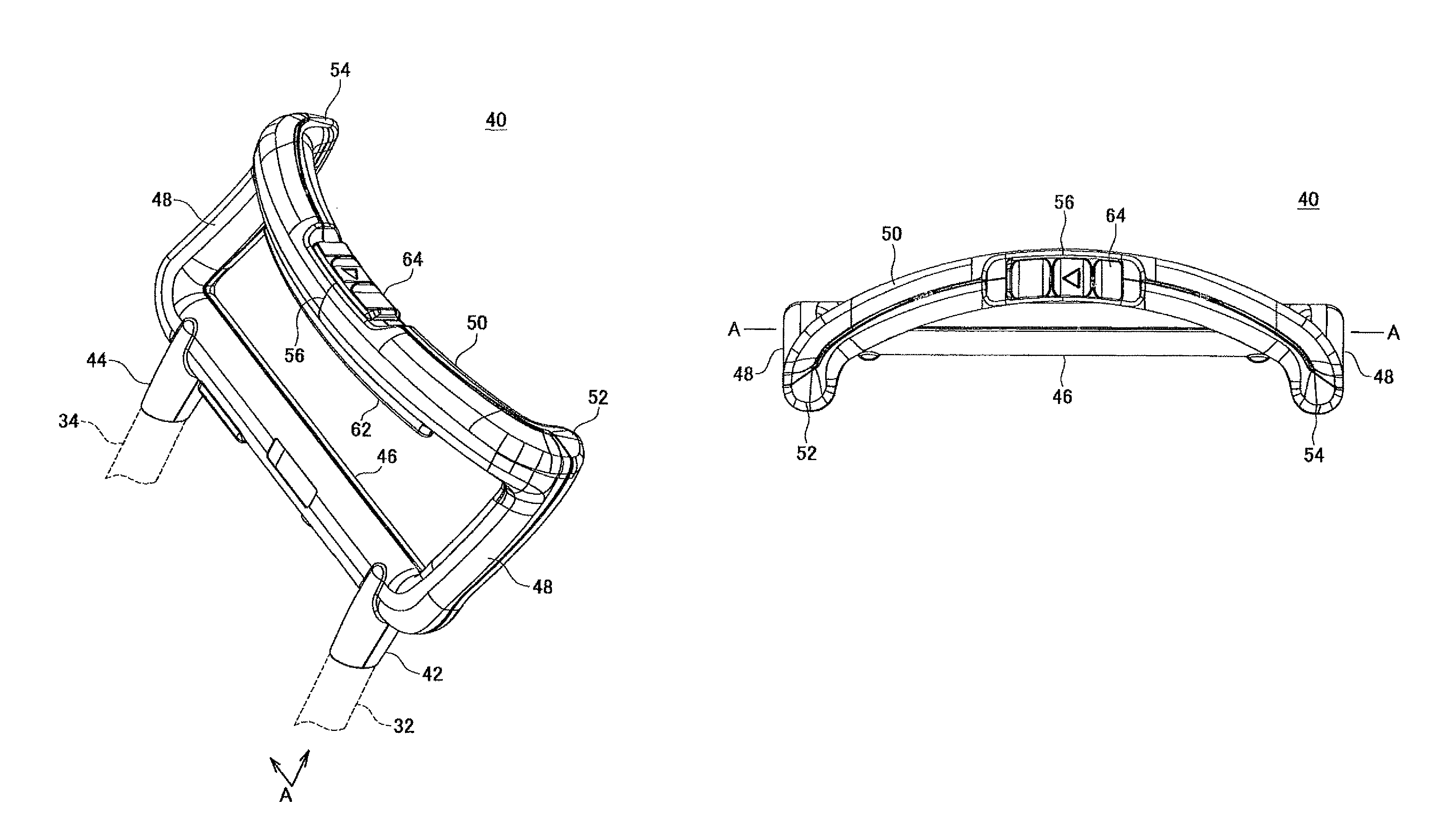
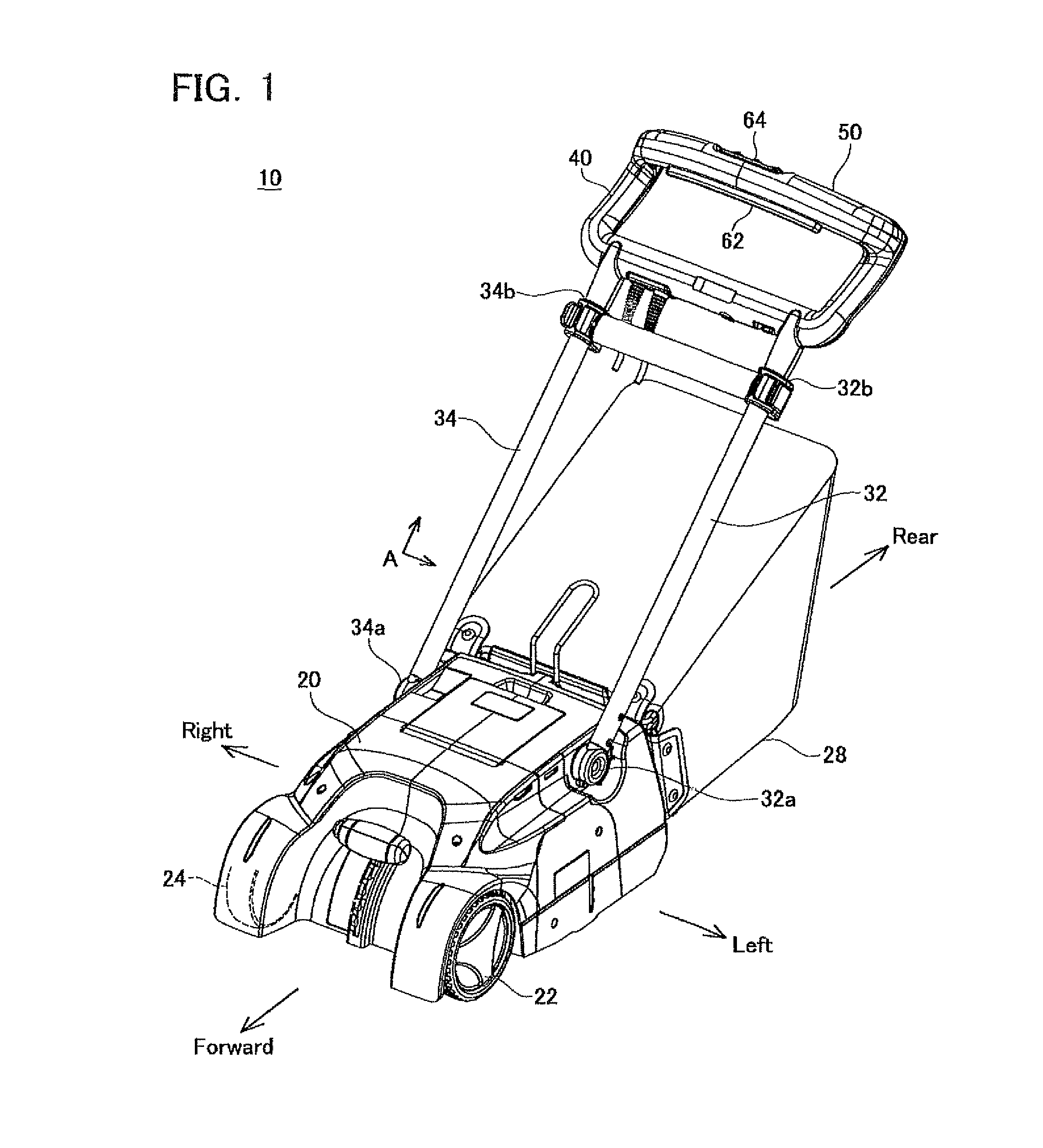
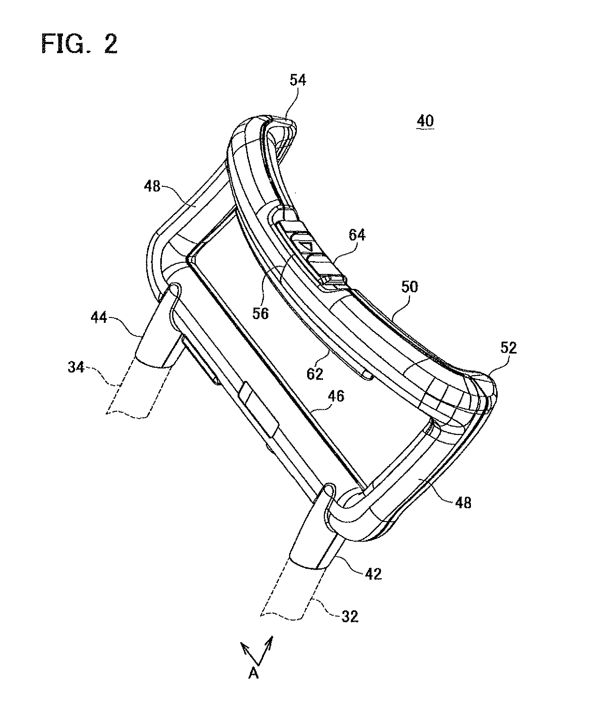
[0026]FIG. 1 shows a mower 10 according to an embodiment. The mower 10 is of a push type (walk-behind type). Thus, the user mows the lawn, by walking, while pushing the mower 10.

[0027]As shown in FIG. 1, the mower 10 includes a mower main body 20, a left arm 32 and a right arm 34 extending upward toward a rear side from the mower main body 20, a handle unit provided at the left arm 32 and the right arm 34, and a grass collecting bag 28 provided at the rear side of the mower main body 20. The mower main body 20 has a plurality of wheels 22, 24 (some of the wheels are not shown in the figure) and is configured to be capable of traveling on the lawn. The mower main body 20 has a blade (not shown in the figure) for cutting the lawn and a motor (not shown in the figure) that drives the blade.

[0028]The left arm 32 and the right arm 34 extend parallel to each other from the mower main body 20. A proximal end 32a of the left arm 32 is attached to the left side surface of the mower main body...


PUM


Abstract

A push mower comprises a mower main body, at least one arm extending upward toward a rear side from the mower main body, and a grip located at a tip end of the at least one arm. Each end of the grip is located on one plane side of an arm plane, a center of the grip is located on an opposite plane side of the arm plane, and therefore the grip extends so as to intersect with the arm plane. Here, the arm plane means a virtual plane on which the at least one arm is located and that is parallel to a left-to-right direction of the mower main body.

Description

CROSS-REFERENCE TO A RELATED APPLICATION[0001]This application claims priority to Japanese Patent Application No. 2010-188451 filed on Aug. 25, 2010, the contents of which are hereby incorporated by reference into the present application.TECHNICAL FIELD[0002]The present invention relates to a push (walk-behind) mower.DESCRIPTION OF RELATED ART[0003]Push mowers are disclosed in Japanese Patent Application Publications No. H11-346530 (Patent Document 1) and No. 2009-225693 (Patent Document 2). These mowers have a mower main body having a blade and an arm extending from the lower main body. A grip that is gripped by the user is provided at a distal end of the arm. The user can cut the lawn by gripping the grip and walking, while pushing the mower.SUMMARY OF THE INVENTION[0004]A grip that is easy to grip and also easy to push is required for a push mower. Accordingly, the present invention provides a grip for a push mower that is easy to grip and push.[0005]In accordance with the presen...

Claims


Application Information

Patent Timeline
Patent Type & Authority Patents(United States)
IPC IPC(8): A01D34/00
CPCA01D34/824
Inventor HACHISUKA, TOMOHIRO
Owner MAKITA CORP
Why Eureka
Try Eureka