Multi-plate clutch system

a multi-plate, clutch technology, applied in the direction of friction clutches, slip couplings, clutches, etc., can solve the problems of sudden movement of pressure plates and rough clutch connection, and achieve the effect of reducing abutment pressure, enhancing spline engagement area, and strengthening the groove forming projecting parts

Inactive Publication Date: 2013-07-23
HONDA MOTOR CO LTD
View PDF5 Cites 2 Cited by
  • Summary
  • Abstract
  • Description
  • Claims
  • Application Information

AI Technical Summary

Benefits of technology

[0019]According to the first aspect of the present invention, the clutch inner and the pressure plate, which is a member different from the clutch inner, are connected together to be unrotatable relative to each other and to be capable of being separated from each other in the axial direction in such a way that, when the assist mechanism increases the pressure-contact force of the pressure plate, the pressure plate is moved in the direction to bring the driving friction plates and the driven friction plates into pressure contact with each other while the clutch inner is moved relative to the pressure plate in the same direction in such a way as to be detached from the pressure plate. For this reason, even if the biasing force of the clutch spring and the retracting force of the assist mechanism act at almost the same time, these forces can be prevented from directly working on the pressure plate. This avoids an abrupt clutch connection, and accordingly makes it possible to achieve an appropriate clutch connection.
[0028]According to the tenth aspect of the present invention, the spaces are formed between the spline projecting parts and the one of the inner periphery of the engagement cylinder part and the outer periphery of the insertion cylinder part, as well as between the groove forming projecting parts and the other of the inner periphery of the engagement cylinder part and the outer periphery of the insertion cylinder part. For this reason, the sliding contact between the sliding-contact surfaces prevents the displacement of the axes of the clutch inner and the pressure plate, and inhibits increase in the area of the slide in the spline engagement area. Furthermore, the use of the spaces as passages through which to flow oil can enhance the slidability and lubricity in the spline engagement area.

Problems solved by technology

This may make the pressure plate move abruptly.
As a result, the clutch connection may be rough.

Method used


Image

  • Multi-plate clutch system
  • Multi-plate clutch system
  • Multi-plate clutch system

Examples


example 1

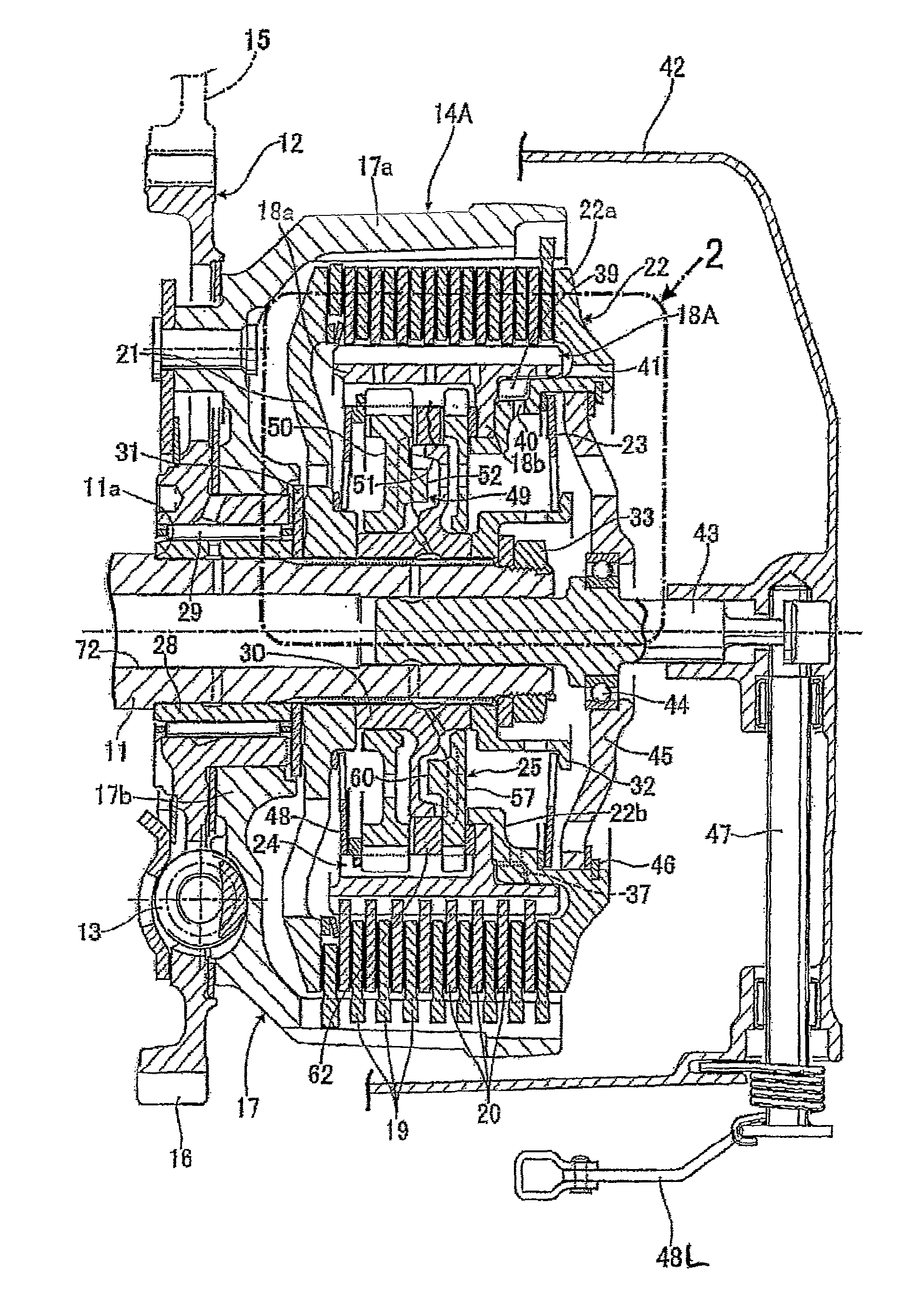
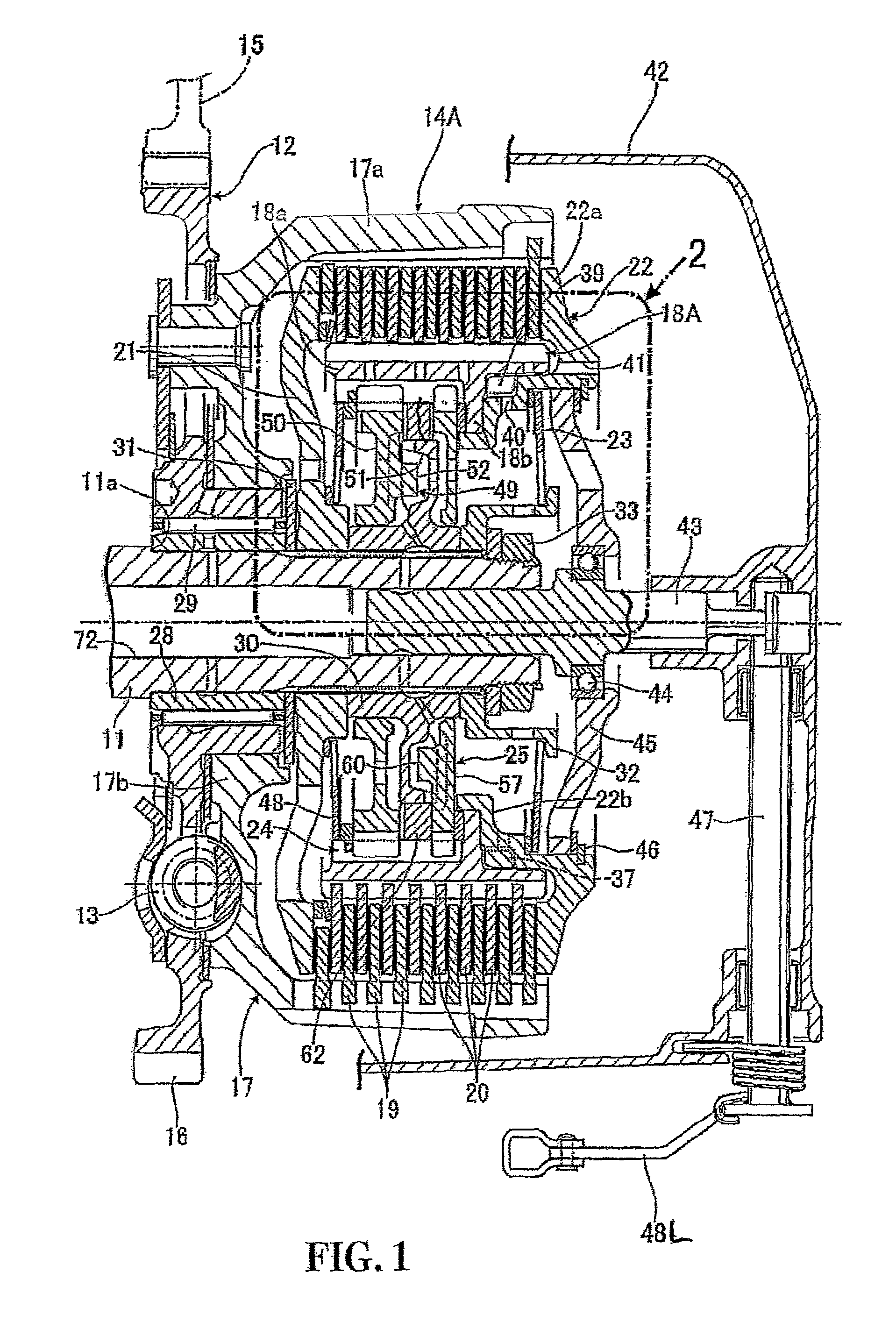
[0039]Example 1 of the present invention will be described by referring to FIGS. 1 to 5. First of all, in FIG. 1, a primary speed reducing device 12, a damper spring 13 and a multi-plate clutch system 14A are installed between a crank shaft (not illustrated) of an engine mounted on, for example, a motorcycle and a main shaft 11 of a gear transmission system (not illustrated). The primary speed reducing device 12 includes: a primary driving gear 15 provided to the crank shaft; and a primary driven gear 16 in mesh with the primary driving gear 15. The primary driven gear 16 is supported by the main shaft 11 in such a way that the primary driven gear 16 is rotatable relative to the main shaft 11.

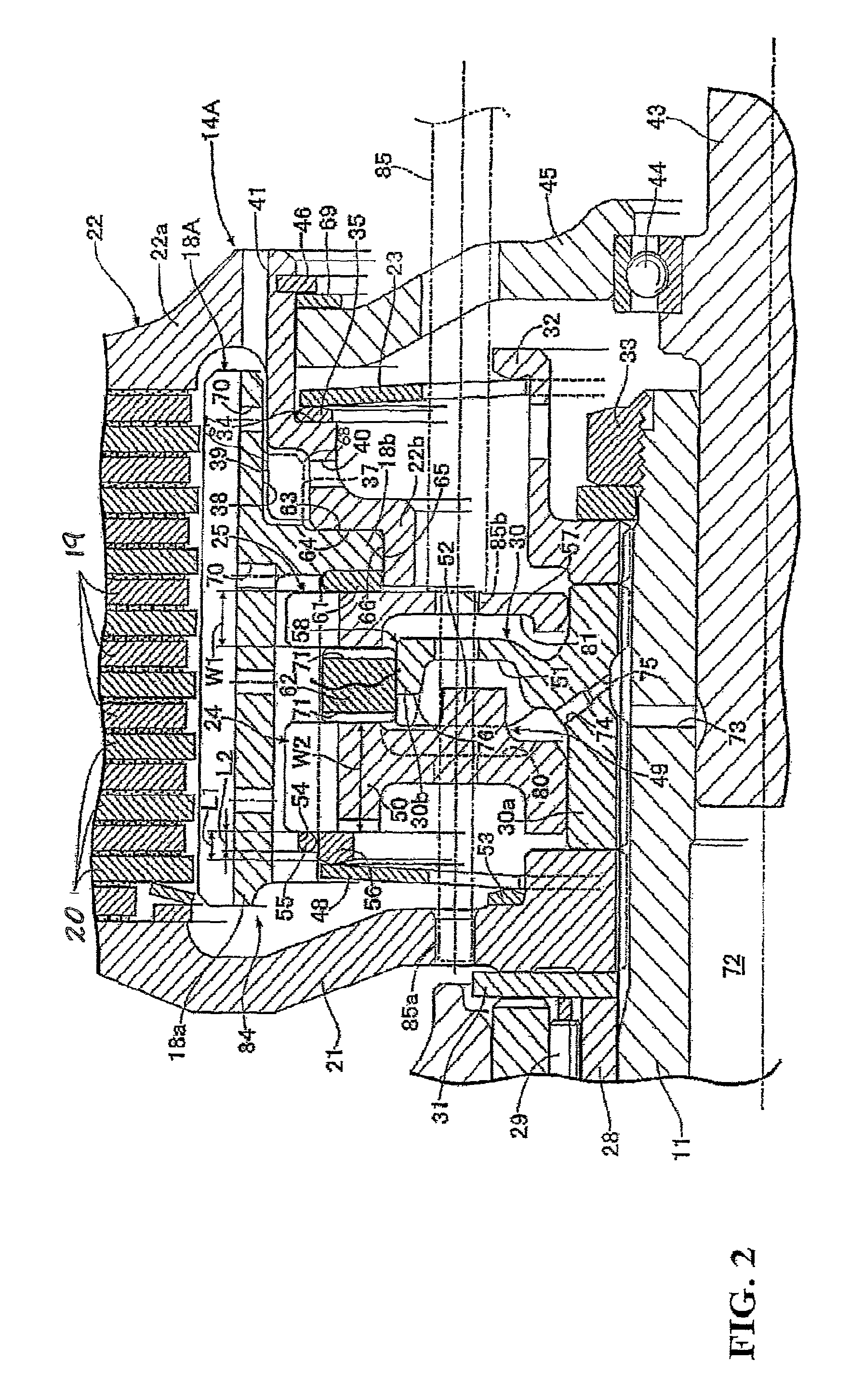
[0040]By referring to FIG. 2, the multi-plate clutch system 14A, which is of a wet-type, includes: a clutch outer 17 connected to the primary driven gear 16, which serves as an input member, with the damper spring 13 in between; a clutch inner 18A which unitarily includes an engagement cylinder...

example 2

[0100]Referring to FIG. 6, descriptions will be provided for Embodiment 2 of the present invention. Parts corresponding to those of Example 1 will be only illustrated with the same reference numerals. Detailed descriptions for such parts will be omitted.

[0101]As through-holes connecting the inner surfaces to the outer surfaces of the first depressed cams 51, oil discharging passages 86 for discharging oil to the sliding-contact area between the inner periphery of the guide ring 62 and the outer periphery of the disc part 30b of the center cam plate 30 are formed in outer peripheral edge portions of the first depressed cams 51 provided in one surface of the disc part 30b of the center cam plate 30 which is common between the assist mechanism 24 and the slipper mechanism 25 included in this multi-plate clutch system 14B, respectively. In addition, similar oil discharging passages (not illustrated) are formed in outer peripheral edge portions of the second depressed cams 59 (see Exampl...

example 3

[0103]Referring to FIG. 7, descriptions will be provided for Embodiment 3 of the present invention. Parts corresponding to those of Examples 1 and 2 will be only illustrated with the same reference numerals. Detailed descriptions for such parts will be omitted.

[0104]A clutch inner 18B included in this multi-plate clutch system 14C unitarily includes: an engagement cylinder part 80a which engages the driven friction plates 20 with its outer periphery; and an annular middle wall 18c projecting inwards from an inner periphery of a middle portion of the engagement cylinder part 80a in the radial direction. An inner periphery of the annular middle wall 18c is in sliding contact with the outer periphery of the center cam plate 30 which is common between the assist mechanism 24 and the slipper mechanism 35.

[0105]In addition, the stop ring 55, 87 engaged with the assist cam plate 50 and slipper cam plate 57 from the opposite sides from the annular middle wall 18c are put on the assist cam p...


PUM


Abstract

A pressure plate is movable in an axial direction to cause multiple driving friction plates and driven friction plates to come in pressure contact with each other. The pressure plate is biased by a clutch spring in a direction to bring the driving friction plates and the driven friction plates in pressure contact with each other. When acceleration torque is changed, an assist mechanism increases the pressure-contact force of the pressure plate. A pressure plate and a clutch inner are connected together and are capable of being separated from each other in an axial direction. When an assist mechanism increases a pressure-contact force of the pressure plate, the pressure plate is moved in a direction to bring driving and driven friction plates into pressure contact with each other, while the clutch inner is moved relative to the pressure plate in the same direction so as to be detached from the pressure plate.

Description

CROSS-REFERENCE TO RELATED APPLICATIONS[0001]This application claims priority under 35 U.S.C. §119(a) to Application No. 2009-227683, filed in Japan on Sep. 30, 2009, the entirety of which is expressly incorporated herein by reference.BACKGROUND OF THE INVENTION[0002]1. Field of the Invention[0003]The present invention relates to a multi-plate clutch system including: a clutch outer connected to an input member; a clutch inner connected to an output member; multiple driving friction plates engaged with the clutch outer in such a way as to be movable in an axial direction, and to be unrotatable relative to the clutch outer; multiple driven friction plates interleaved with the driving friction plates, the driven friction plates being engaged with the clutch inner in such a way as to be movable in the axial direction and to be unrotatable relative to the clutch inner; a pressure plate movable in the axial direction in order to cause the driving friction plates and the driven friction p...

Claims


Application Information

Patent Timeline
Patent Type & Authority Patents(United States)
IPC IPC(8): F16D13/54F16D43/21F16D13/74
CPCF16D13/56F16D2013/565
Inventor GOKAN, YOSHITSUGUMIYAZAKI, JUNSHIOMI, YOSHINOBU
Owner HONDA MOTOR CO LTD
Why Eureka
Try Eureka