Bone compression and distraction system

a distraction system and compression technology, applied in the field of bone compression and distraction medical instruments, can solve the problems of increasing the involvement of personnel, requiring more applied force, and not as effective methods, and achieve the effect of positive cost impa

Active Publication Date: 2013-07-23
LITHOS SURGICAL INNOVATIONS
View PDF3 Cites 6 Cited by
  • Summary
  • Abstract
  • Description
  • Claims
  • Application Information

AI Technical Summary

Benefits of technology

[0030]Additionally, the apparatus and system of the present disclosure is made from fewer parts than many prior art devices, which can have a positive impact on costs. Additionally, due to the construction, the bone compression and distraction apparatus of the present invention can be made smaller than conventional devices and can be utilized in procedures performed on smaller joints. There is a plurality of access slots and an assembly slot along the body of the bone compression and distraction apparatus, which helps the process of cleaning and sterilizing. It is contemplated that the apparatus is provided in a plastic box to hold the components when not in use. The box has openings on its outer surface, which allows the disclosure to be cleaned and sterilized when stored within the box.

Problems solved by technology

These methods are not as effective and require more applied force, more personnel involvement, and obstruct the surgical field view.
Problematically, many bone compression and distraction instruments are excessively large, which preclude their use for smaller joints, maxillofacial, podiatric, or hand surgeries.
However, there are some smaller bone compression and distraction instruments, but they are often composed of complex assemblies and require a large number of parts which can prove quite costly.
Additionally, many bone compression and distraction instruments are hard to clean and sterilize.

Method used


Image

  • Bone compression and distraction system
  • Bone compression and distraction system
  • Bone compression and distraction system

Examples


Embodiment Construction

[0047]While this invention is susceptible of embodiment in many different forms, there is shown in the drawings and described herein in detail a specific embodiment with the understanding that the present disclosure is to be considered as an exemplification and is not intended to be limited to the embodiment illustrated.

[0048]It will be understood that like or analogous elements and / or components, referred to herein, may be identified throughout the drawings by like reference characters. In addition, it will be understood that the drawings are merely schematic representations of the invention, and some of the components may have been distorted from actual scale for purposes of pictorial clarity.

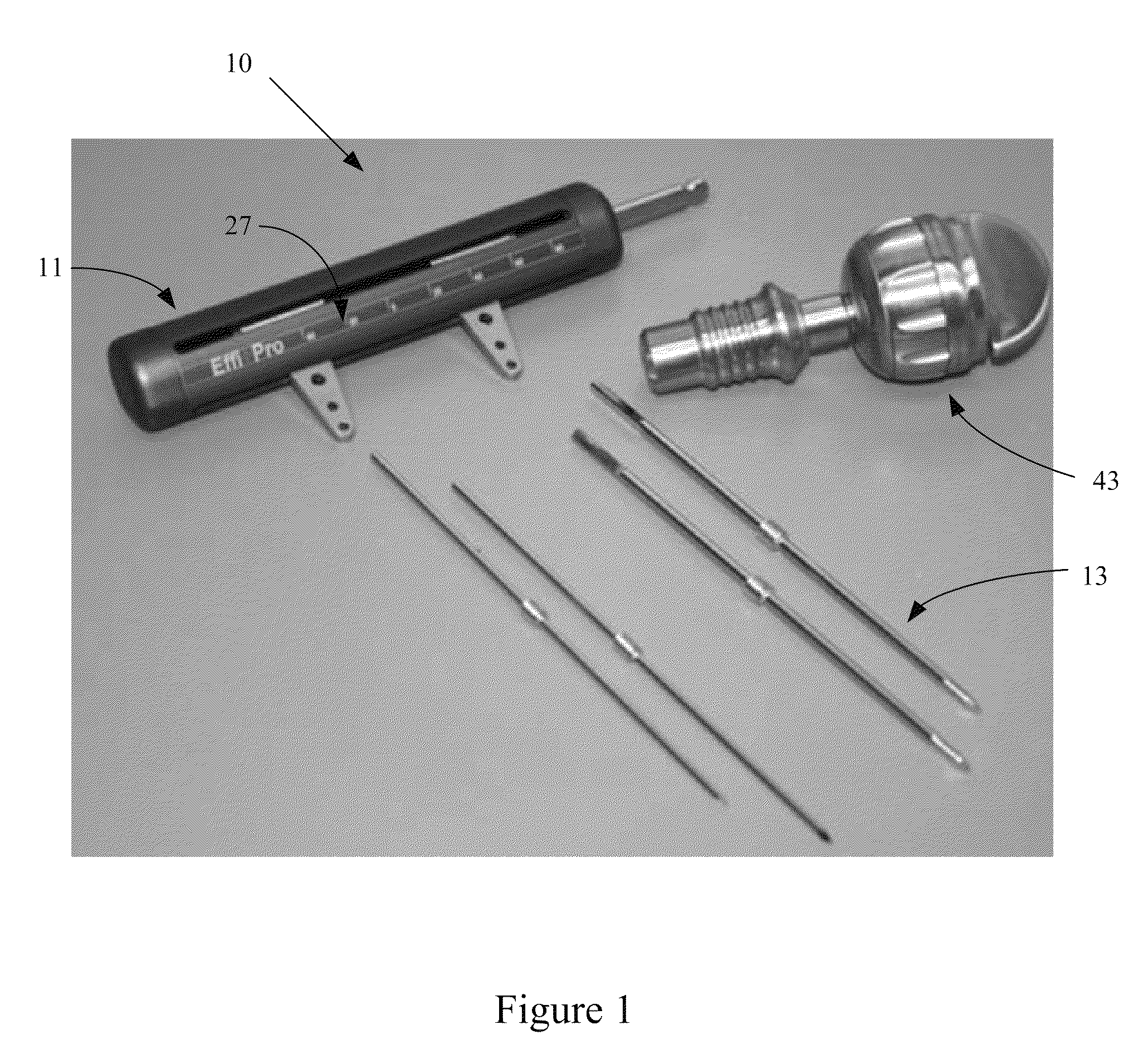
[0049]Bone compression and distraction system 10 is shown in FIG. 1 as comprising bone compression and distraction apparatus 11 and a plurality of pins, such as pin 13. A ratchet 43 may also be provided to manipulate the apparatus. The system comprises a light-weight apparatus that provides b...


PUM


Abstract

A bone compression and distraction system which has an apparatus and a plurality of pins. The apparatus includes a body, a worm screw and a pair of pin attachment members. The worm screw is placed in the body and the pin attachment members are coupled to the worm screw, and constrained from rotation relative to the worm screw, wherein the worm screw has opposing threads extending away from a central region. Upon rotation of the worm screw, the pin attachment members travel in opposite directions, either toward each other or away from each other to either decrease or increase the spacing therebetween. A pin may be coupled to each of the pin attachment members.

Description

CROSS-REFERENCE TO RELATED APPLICATION[0001]This application is a continuation in part of U.S. patent application Ser. No. 12 / 905,310 filed Oct. 15, 2010 now abandoned, entitled Bone Compression and Distraction Apparatus, which claims priority from U.S. Prov. Pat. App. Ser. No. 61 / 279,049 filed Oct. 15, 2009, entitled Bone Compression and Distraction Apparatus, the entire disclosure of each is hereby incorporated by reference.BACKGROUND OF THE DISCLOSURE[0002]1. Field of the Disclosure[0003]The present disclosure is directed toward the field of bone compression and distraction medical instruments and more particularly to a bone compression and distraction system having an apparatus and pin member. The apparatus includes opposing worm gears that provide for micro-adjustable linear compression and distraction as well as improved ease of use.[0004]2. Background Art[0005]The use of bone compression and distraction instruments are well known in the art. Typically, a bone compression and ...

Claims


Application Information

Patent Timeline
Patent Type & Authority Patents(United States)
IPC IPC(8): A61B17/66
CPCA61B17/66A61B17/68A61B17/6416
Inventor KEILEN, ADAM JOHN
Owner LITHOS SURGICAL INNOVATIONS
Why Eureka
Try Eureka