Scanning mirror based display system and method

a display system and scanning mirror technology, applied in the field of scanning mirror display system and method, can solve the problems of failure to provide accurate information regarding damage to the eyes of the viewers, failure to detect the operation of the movable mirror, etc., and achieve the effect of reducing the impact on the cost of the scanning mirror display system, simple hardware, and greater certainty

Active Publication Date: 2013-07-23
TEXAS INSTR INC
View PDF13 Cites 2 Cited by
  • Summary
  • Abstract
  • Description
  • Claims
  • Application Information

AI Technical Summary

Benefits of technology

[0012]An advantage of an embodiment is that a failure of a scanning mirror may be detected with greater certainty because the light output is measured directly.
[0013]A further advantage of an embodiment is that only simple hardware is required. Therefore, the impact on the cost of the scanning mirror display system may be minimized.
[0014]Yet another advantage of an embodiment is that in addition to detecting failure of a scanning mirror, the embodiment may also be utilized to adjust the performance of the scanning mirror display system.

Problems solved by technology

Extended viewing of the light spot may cause damage to eyes 310 of the viewers.
However, it may be possible for the sensors (the first sensor 211 and the second sensor 216) to fail and provide inaccurate information regarding the operation of the movable mirror 205.

Method used


Image

  • Scanning mirror based display system and method
  • Scanning mirror based display system and method
  • Scanning mirror based display system and method

Examples


Embodiment Construction

[0027]The making and using of the embodiments are discussed in detail below. It should be appreciated, however, that the present invention provides many applicable inventive concepts that can be embodied in a wide variety of specific contexts. The specific embodiments discussed are merely illustrative of specific ways to make and use the invention, and do not limit the scope of the invention.

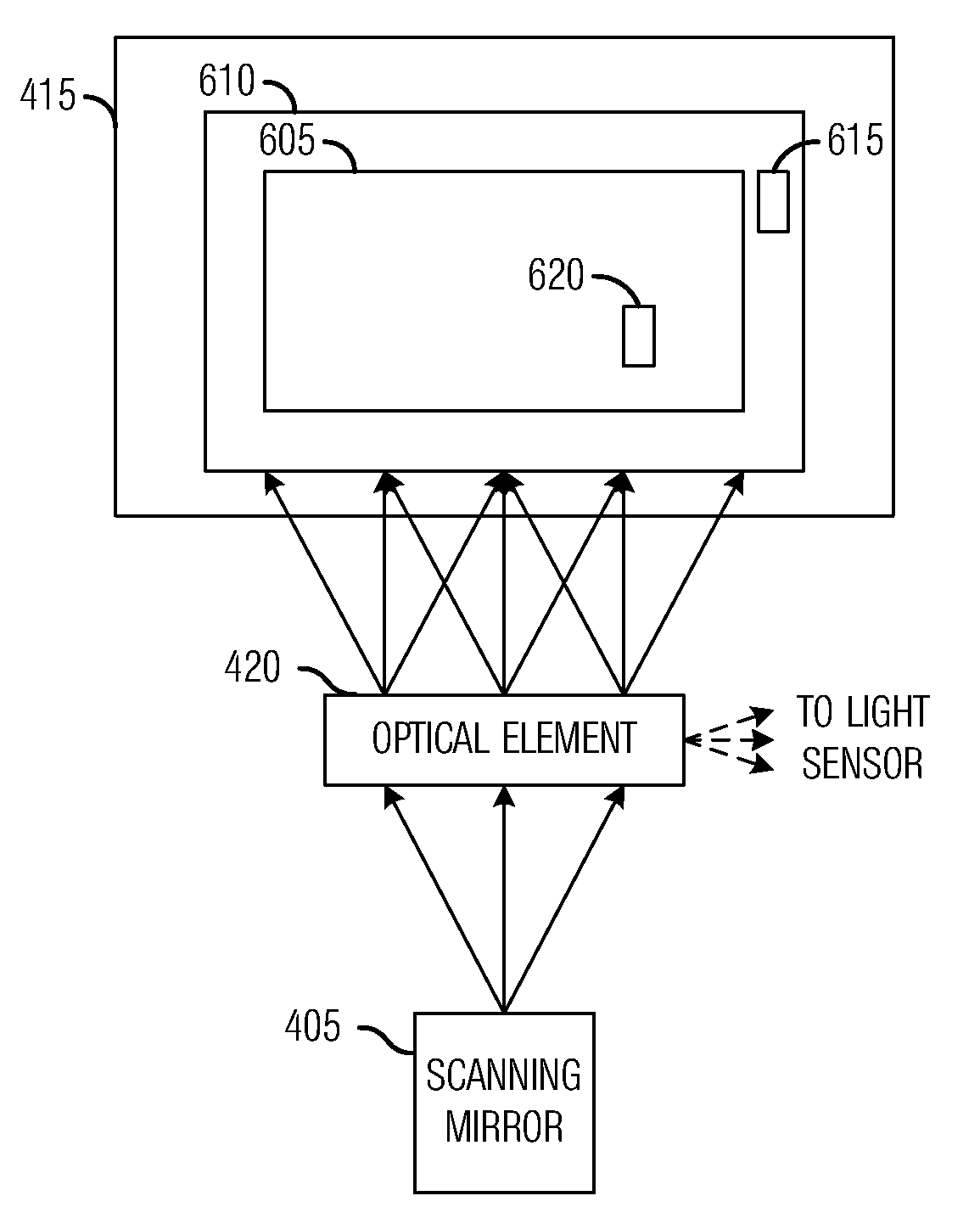
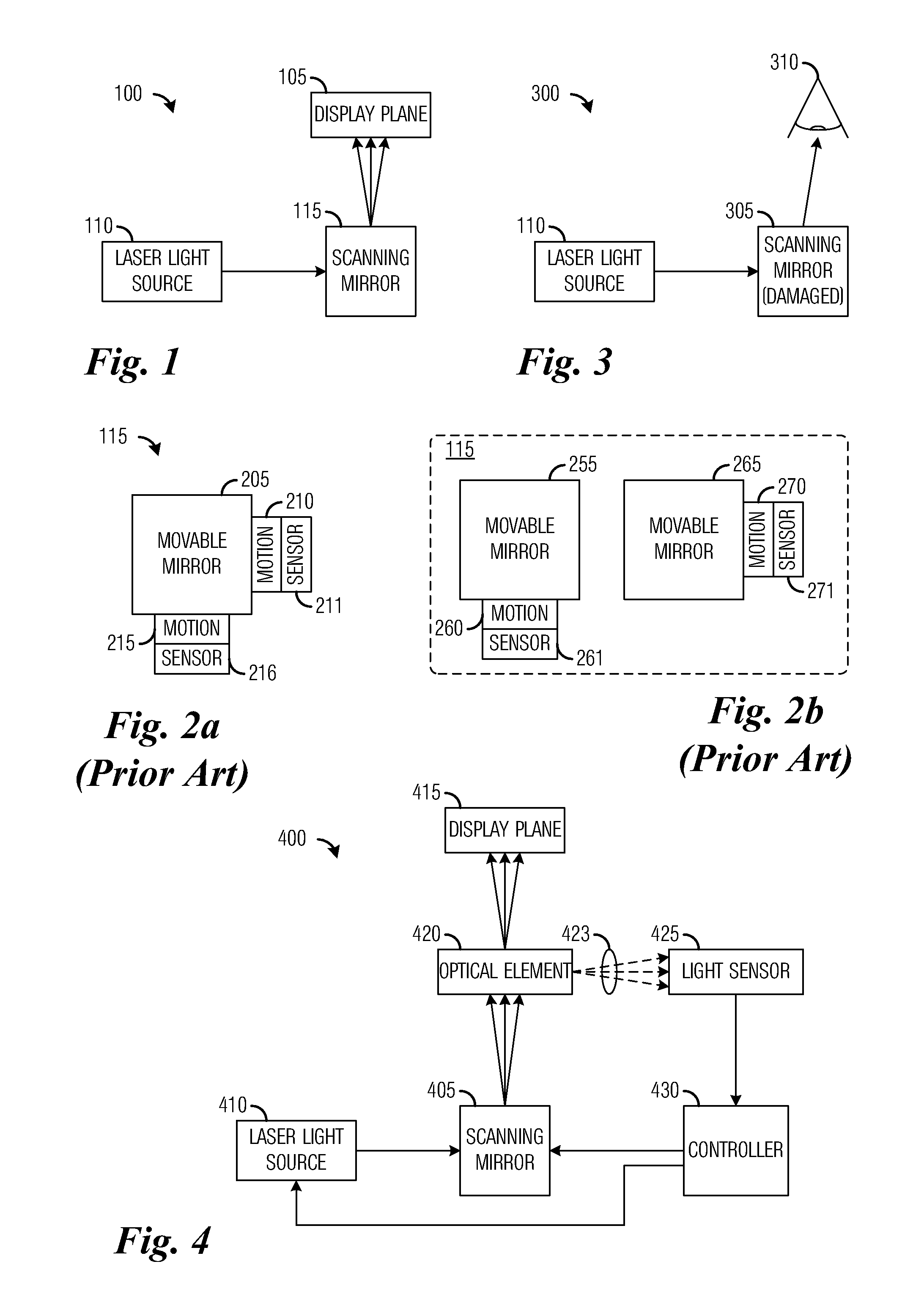
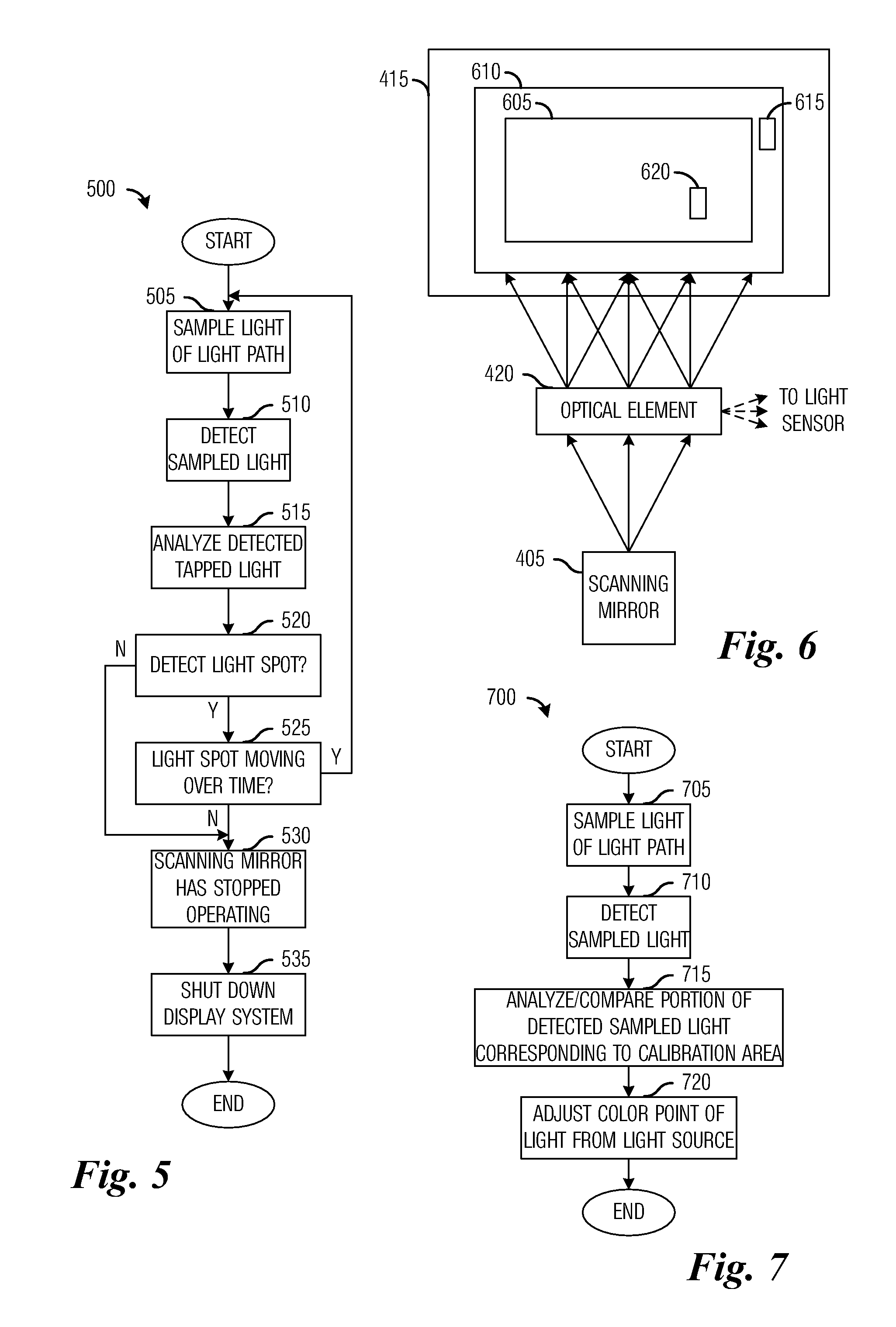
[0028]The embodiments will be described in a specific context, namely a scanning mirror projection display system that scans a light spot to create a two-dimensional image. The display system may be implemented in a wide variety of form factors, ranging from theater models to desktop models to small handheld models. The invention may also be applied, however, to other types of projection display systems wherein there is a desire to adjust optical performance through an optical feedback system, including scanning mirror projection display systems, that scan a line or spot of light to create a two...


PUM


Abstract

Scanning mirror based display system and method. A method comprises sampling a scanned light provided by a scanning mirror, converting the sampled scanned light into an electrical signal, analyzing the electrical signal to determine a position of the scanned light, and controlling the light source or the scanning mirror based on the analyzed electrical signal. The electrical signal based on the sampled scanned light may be used to ensure proper operation of the scanning mirror display system, such as determining failure of the scanning mirror, proper rendering of colors, determining whether the scanned light is following a desired scan path at a desired scan rate, and so forth.

Description

TECHNICAL FIELD[0001]The present invention relates generally to a system and method for displaying information, and more particularly to a scanning mirror based display system and method.BACKGROUND[0002]Projection display systems illuminated by laser light may use a microdisplay, such as a digital micromirror device (DMD), transmissive or reflective liquid crystal display (LCD), liquid crystal on silicon (LCoS), ferroelectric liquid crystal on silicon, deformable micromirrors, and so forth, or a scanning mirror to generate an image on a display plane. In general, a microdisplay in a projection display system will create a miniature version of the image to be displayed and through the use of optical lenses and elements, project an enlarged version of the image on the display plane.[0003]FIG. 1 illustrates a simplified scanning mirror display system 100. The scanning mirror display system 100 may create an image on a display plane 105 by scanning a light spot created by a light source...

Claims


Application Information

Patent Timeline
Patent Type & Authority Patents(United States)
IPC IPC(8): G09G3/00
CPCG01J1/32G01J1/4228G03B21/28G01J2001/0276G02B26/10
Inventor OVERMANN, SCOTT PATRICKMORGAN, DANIEL J.
Owner TEXAS INSTR INC
Why Eureka
Try Eureka