Radar System For Detecting Profiles Of Objects, Particularly In A Vicinity Of A Machine Work Tool

a technology of a radar system and an object, applied in the field of radar systems, can solve the problems of high peak power, large instantaneous bandwidth and high peak power, waste of energy, etc., and achieve the effects of reducing sampling frequency, low bandwidth, and reducing cos

Active Publication Date: 2019-05-02
RODRADAR LTD
View PDF5 Cites 1 Cited by
  • Summary
  • Abstract
  • Description
  • Claims
  • Application Information

AI Technical Summary

Benefits of technology

[0007]The use of a direct digital synthesiser to generate an intermediate frequency (I.F.) off-set frequency; an up-converter comprising a quadrature mixer, single-side mixer or complex mixer to add the off-set frequency to the transmitted frequency; and a down-converter in the receive path driven by the off-set frequency as a local oscillator, enables the received information to be transferred to the I.F. frequency. This in turn can be sampled synchronously in such a way as to provide a complex data stream carrying amplitude and phase information. In this way, there is no need for a second receiver to recover the transmitted phase since phase coherence is intrinsic to the scheme. Accordingly, the system is implementable with only a single transmit channel and a single receive channel.
[0008]Furthermore, the radar system is implementable using a single analogue printed circuit board (PCB) and a single digital PCB. Moreover, the low bandwidth achieved using low frequency I.F. reduces the sampling frequency required in digitising so that the data transfer between the analogue and digital PCBs is achievable via the serial programmable interface (SPI) of the digital PCB. This has a beneficial impact on cost since the need for custom interface circuitry is removed.
[0009]Accordingly, the radar system of the present disclosure is low power, low data bandwidth and low cost, while achieving a high measurement bandwidth at radio frequency (R.F.).

Problems solved by technology

To obtain high resolutions, such systems require large instantaneous bandwidth and high peak power.
This results in a wastage of energy since the interval of echo delay must be visited sequentially, whereas each transmission penetrates and excites echoes from the entire delay space.
However, stepped frequency radar systems tend not to be employed in small scale, low cost radar systems because of difficulties in implementation, generally resulting in higher cost.
This arrangement, however, introduces substantial complexity because of the need to match the two receivers accurately.
Digital frequency generation (Direct Digital Synthesis (DDS)) is not capable of operating directly at the frequencies required for a ground penetrating radar and requires at least frequency doubling, which is costly.

Method used


Image

  • Radar System For Detecting Profiles Of Objects, Particularly In A Vicinity Of A Machine Work Tool
  • Radar System For Detecting Profiles Of Objects, Particularly In A Vicinity Of A Machine Work Tool
  • Radar System For Detecting Profiles Of Objects, Particularly In A Vicinity Of A Machine Work Tool

Examples


Embodiment Construction

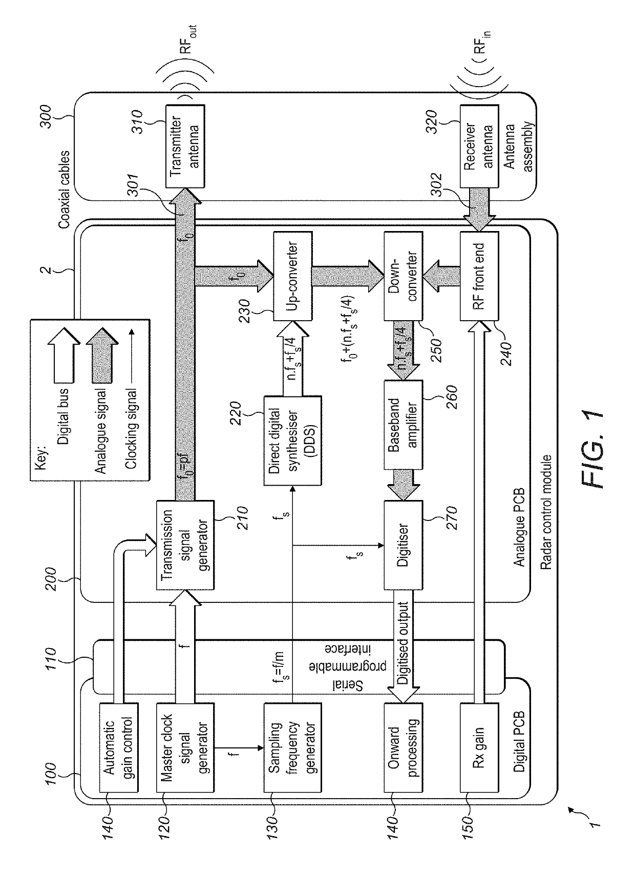
[0020]A radar system 1 in accordance with the present disclosure is shown in a highly schematic fashion in FIG. 1.

[0021]The radar system 1 comprises an antenna assembly 300 and a radar control module 2 comprising a digital PCB 100 and an analogue PCB 200.

[0022]The antennal assembly may comprise a transmitter antenna 310 and a receiver antenna 320. The transmitter antenna 310 may be configured to transmit electromagnetic radiation into the environment surrounding the transmitter antenna 310. The receiver antenna 320 may be configured to receive electromagnetic radiation from the environment surrounding the receiver antenna 320. The transmitter antenna 310 and receiver antenna 320 may be highly directional and co-directed such that the receiver antenna 320 is located so as to receive echoes of electromagnetic radiation emitted by the transmitter antenna 310.

[0023]The digital PCB 100 may be an off-the-shelf digital PCB comprising a serial programmable interface 110 by which data may be...


PUM


Abstract

A radar system is disclosed for detecting profiles of objects, particularly in a vicinity of a machine work tool. The radar system uses a direct digital synthesiser to generate an intermediate frequency off-set frequency. It also uses an up-converter comprising a quadrature mixer, single-side mixer or complex mixer to add the off-set frequency to the transmitted frequency. It further uses a down-converter in the receive path driven by the off-set frequency as a local oscillator. The radar system enables received information to be transferred to the intermediate frequency. This in turn can be sampled synchronously in such a way as to provide a complex data stream carrying amplitude and phase information. The radar system is implementable with a single transmit channel and a single receive channel.

Description

TECHNICAL FIELD[0001]The disclosure relates to the field of radar systems, particularly for compact, close range applications. One application would be ground penetration radar in the context of a machine work tool such as an excavator bucket.BACKGROUND[0002]Radar systems that detect the presence of objects in an environment are well known, including ground penetrating radar systems. The majority of such systems employ a pulsed radar technique, such that they transmit a train of short pulses (impulses) of electromagnetic energy with a high peak power (e.g. of the order of tens of kilowatts). The pulse energy is reflected by dielectric discontinuities such that the radar receives echoes in one to one correspondence with the transmitted pulses. This energy is reflected by dielectric discontinuities and received by the radar to produce a profile of the subsurface objects. This allows a profile of the reflecting objects to be produced. Since the time intervals involved are very short (t...

Claims


Application Information

Patent Timeline
Patent Type & Authority Applications(United States)
IPC IPC(8): G01S7/288G01S13/88H03D3/00H03G3/30H01Q1/22
CPCG01S7/288G01S13/885H03D3/007H03G3/3052H01Q1/2283G01S2007/2886G01S13/282E02F3/40E02F9/261G01S7/282G01S13/10G01S13/86G01S7/2886G01S13/34
Inventor CONWAY, SIMONROULSTON, JOHN
Owner RODRADAR LTD
Why Eureka
Try Eureka