Method and apparatus for controlling force feedback interface systems utilizing a host computer

a technology of interface system and host computer, applied in the field of interface devices, can solve the problems of difficult to provide realistic bumpiness feeling, complex robotic mechanism which requires precision components and expensive actuators, and the typical slow speed of standard serial communication interfaces, etc., to achieve more realistic and accurate force feedback, save significant processing time on the host computer, and facilitate creation

Inactive Publication Date: 2006-01-03
IMMERSION CORPORATION
View PDF153 Cites 73 Cited by
  • Summary
  • Abstract
  • Description
  • Claims
  • Application Information

AI Technical Summary

Benefits of technology

[0015]The invention also provides a paradigm for force commands between the host computer and the local microprocessor. The high level host commands provided by the host computer can be rate control and / or position control commands, and may include information in the form of command parameters. By providing a relatively small set of commands and command parameters which are translated into a panoply of forces, the paradigm further shifts the computational burden from the host computer to the local microprocessor. Host commands may include commands to provide forces on the user object such as restoring forces, vibration forces, texture forces, a barrier forces, attractive / repulsive force fields, damping forces, groove forces, and a paddle-ball force. Typical command parameters include a magnitude parameter, a duration parameter, a direction parameter, a style parameter, and a button parameter to control the force output by the actuator. This provides a high level, standard force feedback command protocol for the efficient use by developers of force feedback software to be implemented on the host computer system.
[0017]The control system and method of the present invention advantageously includes a separate processor local to the interface device that is separate from the host computer system. The local processor can read and process sensor signals as well as output force command signals independently of the host computer, thus saving significant processing time on the host computer. In addition, the use of the local processor to handle low-level force feedback commands allows more realistic and accurate force feedback to be provided to an object manipulated by a user when using a serial or other relatively low-bandwidth communication interface between the host and the interface device, since such low level force signals do not have to be transmitted over the communication interface. The use of specific, high level host commands to command a variety of types of forces allows force feedback host applications to be easily created. These improvements allow a computer system to provide accurate and realistic force feedback over a low-cost, low bandwidth communication interface and is thus ideal for the mass market of home computer systems.

Problems solved by technology

This is because most of the force feedback devices have been targeted at the specific needs of highly industrial applications, and not a mass consumer market.
As a result, typical force feedback interface devices include complex robotic mechanisms which require precision components and expensive actuators.
If the control signals are too slow, a realistic feeling of bumpiness is more difficult to provide.
A problem is evident when prior art force feedback interface devices are provided to the mass consumer market.
However, these standard serial communication interfaces are typically quite slow (i.e. have low bandwidth) compared to other communicaton interfaces.
Realistic and accurate force feedback thus becomes difficult to provide by a controlling computer system to a prior art interface device connected through such a serial interface.
Such a device is not suitable for a low bandwidth communication interface to achieve realistic force feedback.
Another problem with using prior art force feedback interface devices in the mass consumer market is the wide variety of computer platforms and processing speeds that are used on different computers and on the same computer at different times. The force sensations provided to a user by a force feedback interface device may feel different to a user on different computer platforms or microprocessors, since these different computers run at different speeds.
In addition, there is no standardized language or communication protocol for communicating with force feedback devices.
This requires unnecessary time and expense in the development of software applications that include features directed toward force feedback interfaces.

Method used


Image

  • Method and apparatus for controlling force feedback interface systems utilizing a host computer
  • Method and apparatus for controlling force feedback interface systems utilizing a host computer
  • Method and apparatus for controlling force feedback interface systems utilizing a host computer

Examples


first embodiment

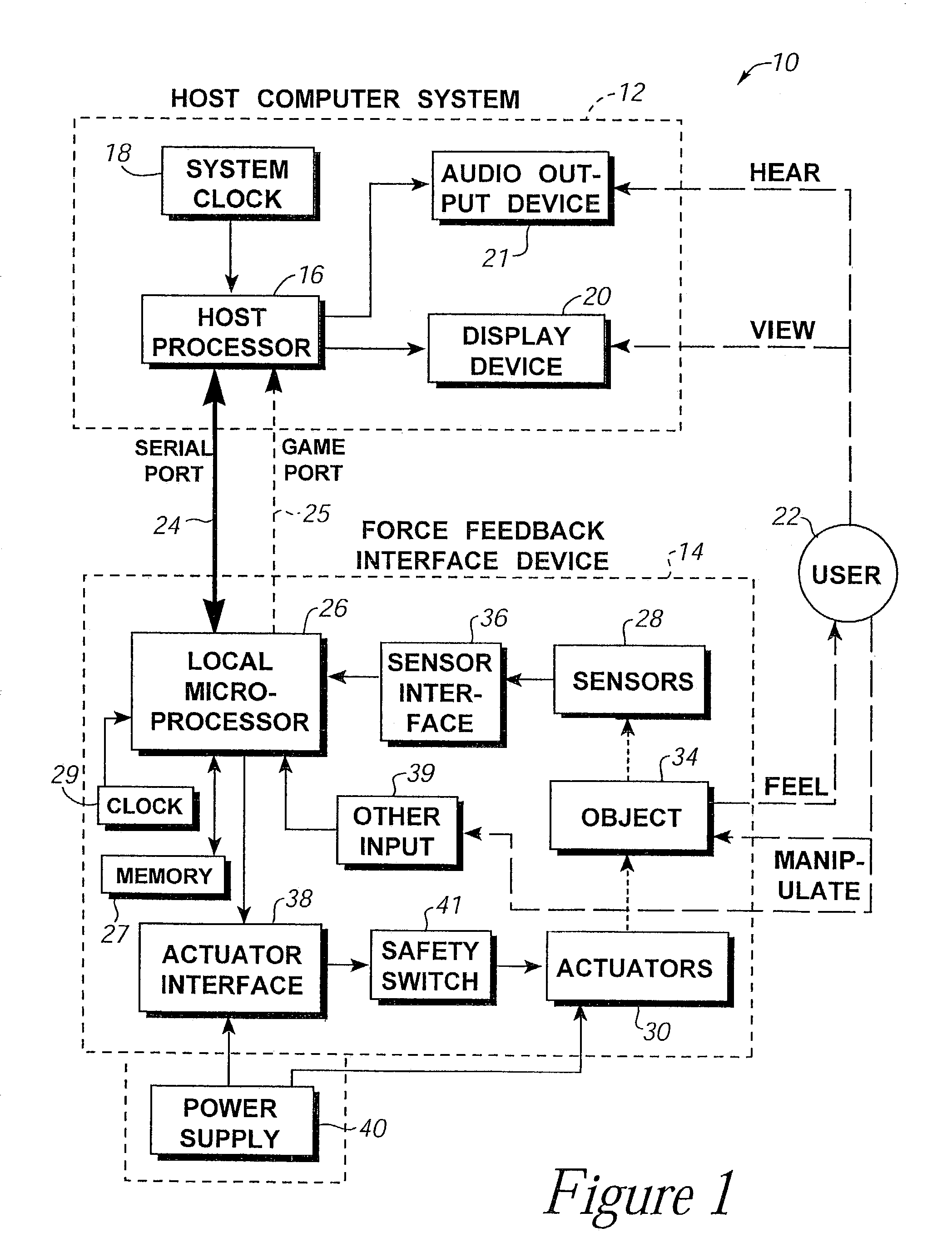
[0080]FIG. 4 is a flow diagram illustrating a method 70 for controlling a force feedback interface device of the present invention. Method 70 is directed to a “host-controlled” embodiment, in which host computer system 12 provides direct, low-level force commands to microprocessor 26, and the microprocessor directly provides these force commands to actuators 30 to control forces output by the actuators.

[0081]For example, the host controlled mode is suitable for embodiments using a USB communication interface. Data rates are sufficiently high to allow the host to communicate at 500 Hz or greater and provide realistic force feedback to the user object 34. The USB Isochronous Data Transfer mode of USB is suitable to provide the necessary high data rate.

[0082]The process begins at 72. In step 74, host computer system 12 and interface device 14 are powered up, for example, by a user activating power switches. After step 74, the process 70 branches into two parallel (simultaneous) process...

second embodiment

[0106]FIG. 5 is a flow diagram illustrating a method 100 for controlling force feedback interface device 14 of the present invention. Method 100 is directed to a “reflex” embodiment, in which host computer system 12 provides only high-level supervisory force commands (“host commands”) to microprocessor 26, while the microprocessor independently determines and provides low-level force commands (force values) to actuators 30 as an independent “reflex” to control forces output by the actuators.

[0107]The process of FIG. 5 is suitable for low speed communication interfaces, such as a standard RS-232 serial interface. However, the embodiment of FIG. 5 is also suitable for high speed communication interfaces such as USB, since the local microprocessor relieves computational burden from host processor 16. In addition, this embodiment can provide a straightforward command protocol, an example of which is described with respect to FIGS. 9 and 14, and which allow software developers to easily ...


PUM


Abstract

A method and apparatus for controlling and providing force feedback using an interface device manipulated by a user. A microprocessor is provided local to the interface device and reads sensor data from sensors that describes the position and / or other information about a user object moved by the user, such as a joystick. The microprocessor controls actuators to provide forces on the user object and provides the sensor data to a host computer that is coupled to the interface device. The host computer sends high level host commands to the local microprocessor, and the microprocessor independently implements a local reflex process based on the high level command to provide force values to the actuators using sensor data and other parameters. A provided host command protocol includes a variety of different types of host commands and associated command parameters. By providing a relatively small set of high level host commands and parameters which are translated into a panoply of forces, the protocol further shifts the computational burden from the host computer to the local microprocessor and allows a software developer to easily create force feedback applications.

Description

CROSS REFERENCE TO RELATED APPLICATIONS[0001]This application is a continuation of U.S. patent application Ser. No. 09 / 815,872, filed Mar. 22, 2001, now U.S. Pat. No. 6,580,417, which is a continuation of parent U.S. patent application Ser. No. 09 / 050,665, filed Mar. 30, 1998, now U.S. Pat. No. 6,219,033, which is a continuation of U.S. patent application Ser. No. 08 / 566,282, filed Dec. 1, 1995, now U.S. Pat. No. 5,734,373, which is a continuation-in-part of U.S patent applications Ser. No. 08 / 534,791, filed Sep. 27, 1995, now U.S. Pat. No. 5,739,811, and A CIP of Ser. No. 08 / 461,170, filed Jun. 5, 1995, now U.S. Pat. No. 5,576,727, which is a continuation of application Ser. No. 08 / 092,974, filed Jul. 16, 1993, now abandoned, all of which are incorporated herein by reference in their entirety.BACKGROUND OF THE INVENTION[0002]The present invention relates generally to interface devices between humans and computers, and more particularly to computer interface devices that provide for...

Claims


Application Information

Patent Timeline
Patent Type & Authority Patents(United States)
IPC IPC(8): G06F3/033G09G5/08A63F13/06B25J9/16G01B5/008G01B7/004G01B21/04G05B19/42G05D25/02G05G9/047G06F3/00G06F3/01G06F3/038
CPCA63F13/06B25J9/1692G01B5/008G01B7/004G01B21/04G05B19/4207G05D25/02G05G9/047G06F3/011G06F3/016G06F3/038G06F3/0383H01H2003/008A63F2300/1037A63F2300/1043G05G2009/04766G05G2009/04777G06F2203/014G06F2203/015A63F2300/1025A63F2300/1006A63F13/803A63F2300/8017A63F2300/64A63F2300/8082A63F13/285A63F13/23A63F13/24A63F13/57A63F13/21
Inventor ROSENBERG, LOUIS B.BRAUN, ADAM C.LEVIN, MIKE D.
Owner IMMERSION CORPORATION
Why Eureka
Try Eureka