Apparatus and method for micromanipulation of microscale objects using laser light delivered through a single optical fiber and axicon lens

a technology of laser light and micro-objects, applied in the field of single-fiber optical tweezers, can solve the problems of reducing requiring large processing time for groups of cells, and complex control of the scanning beam by computer, so as to reduce the throughput of the laser microbeam system, and achieve high throughput. the effect of large processing tim

Active Publication Date: 2013-10-29
RGT UNIV OF CALIFORNIA
View PDF5 Cites 3 Cited by
  • Summary
  • Abstract
  • Description
  • Claims
  • Application Information

AI Technical Summary

Benefits of technology

[0011]The illustrated embodiment of the present invention is a simple-to-operate device which uses a spatially shaped elongated laser focused spot for micro-dissection of living / nonliving microscopic objects with high throughput. In the past, either a scanning stage or scanning mirror was used to scan a region in a single cell or group of cells for microprocessing and / or microdissection. Besides being expensive, the prior art approach requires complex control of the scanning beam via computer. Most importantly, the above mentioned techniques require large processing time for groups of cells. This reduces the throughput of the laser microbeam system. Further, this may lead to the requirement of immobilization (by optically trapping or otherwise) of the motile object(s) for precise micro-dissection.
[0012]The illustrated embodiment of the invention is a device and method that uses a spatially shaped laser beam (generated simply by insertion of a cylindrical lens) for manipulation, micro-dissection, alteration / ablation, and excitation of living or nonliving microscopic objects with high throughput. To achieve the spatial shaped laser beam, the N2 pulsed UV-laser beam was focused to a linear profile by use of a cylindrical lens. For optical trapping of the objects in suspension, a CW NIR laser beam was also aligned with the UV laser scissors beam by use of a dichroic mirror. This elongated UV (and or NIR) laser beam was relayed to the back aperture of a high NA Zeiss microscope objective via the epi-fluorescence port. The cylindrical lens was mounted on a motorized rotational stage so as to enable controlled orientation of the direction of elongation in the x-y plane. A variable aperture (VAP) was placed at the focal plane of the cylindrical lens in order to control the length of the focused spot. For fluorescence imaging, light from a mercury lamp was collimated and coupled to the microscope by use of a dichroic mirror that reflects UV (and or NIR), but transmits the visible region of the mercury spectrum. The excitation filter was placed in a filter wheel and another dichroic mirror was used to reflect the fluorescence excitation light, the 337 nm laser scissors beam and optionally the laser tweezers beam. This dichroic mirror transmitted the emitted fluorescence as well as the transmitted halogen light from the sample in the sample chamber. The emission filter also blocked the UV laser scissors and NIR laser tweezers beam. The dimensions of the generated elliptical focused spot determine the length over which the object(s) can be dissected and / or trapped. Use of a 50 mm focal length cylindrical lens in our setup led to a focal spot length of ˜40 / μm at the object plane. The intensity pattern of the elliptically focused UV laser at the focal plane of the objective was monitored by fluorescence excitation of a suitable dye on a coverslip. Control of energy / pulse was achieved by orientation of a polarizer in the beam path. Predetermined numbers of pulses could be delivered through external triggering of the laser by use of National Instrument's data acquisition and control board. While the dimension of the line scissors could be easily varied by controlling the size of the aperture (VAP), control on orientation of the cuts required rotation of the cylindrical lens manually or by use of a rotatable stepper motor.
[0013]One of the purposes of the illustrated embodiment of the invention is to develop a device for fast patterned linear ablation of microscopic objects which is simple to operate and provides high throughput in a uniform manner.
[0015]The fundamental principle exploited is that by shaping the pulsed laser beam into a linear profile via a cylindrical lens, line scissors can be achieved that provides simple and fast line patterned ablation as compared to scanning the beam with motorized stage or scanning mirror. While the dimension of the line scissors can be easily varied by controlling the size of a circular aperture in the beam path, control of orientation of the line cuts requires rotation of the cylindrical lens achieved by use of a rotating mount.
[0016]The advantages of the present invention include (1) fast patterned linear ablation of microscopic objects, (2) simple operation, (3) high throughput in a uniform manner, and (4) less-expense. Uses of the invention include, but are not limited to: (i) induction of DNA damage, (ii) dissection of neuronal axons, (iii) micro-dissection of organelles such as microtubules, (iv) thinning of zona pellucida for use in reproductive medicine, (v) optoporation of exogenous material into cells.

Problems solved by technology

Besides being expensive, the prior art approach requires complex control of the scanning beam via computer.
Most importantly, the above mentioned techniques require large processing time for groups of cells.
This reduces the throughput of the laser microbeam system.
Further, this may lead to the requirement of immobilization (by optically trapping or otherwise) of the motile object(s) for precise micro-dissection.

Method used


Image

  • Apparatus and method for micromanipulation of microscale objects using laser light delivered through a single optical fiber and axicon lens
  • Apparatus and method for micromanipulation of microscale objects using laser light delivered through a single optical fiber and axicon lens
  • Apparatus and method for micromanipulation of microscale objects using laser light delivered through a single optical fiber and axicon lens

Examples


Embodiment Construction

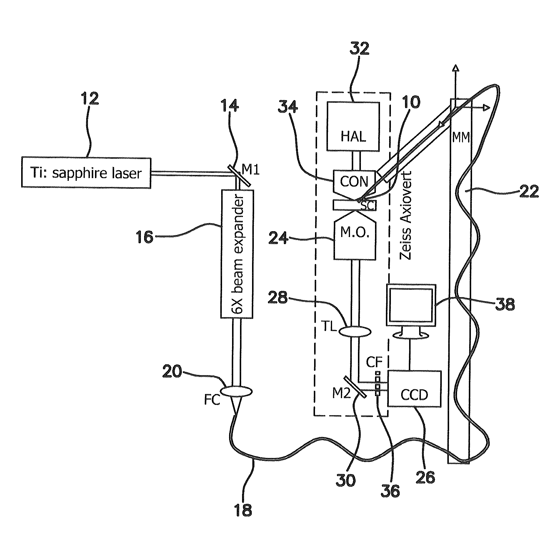
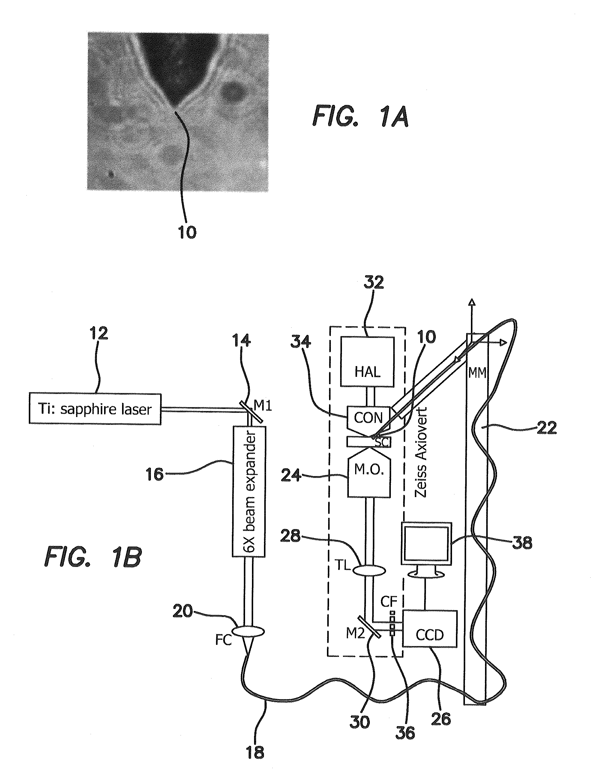
[0033]The short working distance of microscope objectives has severely restricted the application of optical micromanipulation techniques at larger depths. In the illustrated embodiment we show the first use of fiber-optic tweezers toward controlled guidance of neuronal growth cones and stretching of neurons. Further, by mode locking, the fiber-optic tweezers beam was converted to fiber-optic scissors, enabling dissection of neuronal processes and thus allowing study of the subsequent response of neurons to localized injury. At high average powers, lysis of a three dimensionally trapped cell was accomplished.

[0034]In the illustrated embodiment we demonstrate the use of a single fiber-optic axicon device for organization of microscopic objects using longitudinal optical binding. Further, by manipulating the shape of the fiber tip 10, part of the emanating light was made to undergo total internal reflection in the conical tip region, enabling near-field trapping. Near field trapping r...


PUM


Abstract

A single optical fiber having a distal end is optically coupled to the laser and distilling terminated with an axicon lens optically coupled to the single optical fiber to form a microscopic distal tip to provide a spatially shaped elongated laser focused spot for microprocessing and / or microdissection of a microscale object. A pulsed or continuous laser beam or superposition of pulsed and continuous laser beams is generated, controllably spatially shaped, selectively oriented, selectively moved via movement of a single optical fiber terminated with the axicon lens, and the oriented, spatially shaped laser beam applied via the single optical fiber terminated with the axicon lens to a living or nonliving microscopic object for manipulation, micro-dissection, alteration / ablation, and excitation of the living or nonliving microscopic object.

Description

RELATED APPLICATIONS[0001]The present application is related to U.S. Provisional Patent Application Ser. No. 61 / 111,596, filed on Nov. 5, 2008, which is incorporated herein by reference and to which priority is claimed pursuant to 35 USC 119.BACKGROUND OF THE INVENTION[0002]1. Field of the Invention[0003]The invention relates to the field of single-fiber optical tweezers and scissors enabled in-depth multi-functional micro-manipulation of cells.[0004]2. Description of the Prior Art[0005]Optical scissors and tweezers have been tools of the biologist for over two decades. Laser scissors uses lasers to alter and / or to ablate intracellular organelles and cellular and tissue samples, and today have become an important tool for cell biologists to study the molecular mechanism of complex biological systems. Single cells or groups of cells have been perforated for injection of exogenous materials, induction of DNA damage in cells, micro-dissection of neuronal processes as well as other intr...

Claims


Application Information

Patent Timeline
Patent Type & Authority Patents(United States)
IPC IPC(8): G02B6/26G02B6/42
CPCC12M35/02C12N13/00G02B6/262G02B21/32
Inventor MOHANTY, SAMARENDRA K.STEPHENS, JAREDBERNS, MICHAEL W.
Owner RGT UNIV OF CALIFORNIA
Why Eureka
Try Eureka