Force feedback device with microprocessor receiving low level commands

a microprocessor and command technology, applied in the field of interface devices, can solve the problems of difficult to provide realistic bumpiness feeling, complex robotic mechanisms that require precision components and expensive actuators, and the general slowness of standard serial communication interfaces, so as to increase the realism and accuracy of provided forces

Inactive Publication Date: 2006-06-13
IMMERSION CORPORATION
View PDF265 Cites 83 Cited by
  • Summary
  • Abstract
  • Description
  • Claims
  • Application Information

AI Technical Summary

Benefits of technology

[0010]The present invention is directed to controlling and providing force feedback to a user operating a human/computer interface device. The interface device is connected to a controlling host computer and includes a separate micropro...

Problems solved by technology

This is because most of the force feedback devices have been targeted at the specific needs of highly industrial applications, and not a mass consumer market.
As a result, typical force feedback interface devices include complex robotic mechanisms which require precision components and expensive actuators.
If the control signals are too slow, a realistic feeling of bumpiness is more difficult to provide.
A problem is evident when prior art force feedback interface devices are provided to the mass consumer market.
However, these standard serial communication interfaces are typically quite slow (i.e. have low bandwidth) compared to other communicaton interfaces.
Realistic and accurate force feedback ...

Method used


Image

  • Force feedback device with microprocessor receiving low level commands
  • Force feedback device with microprocessor receiving low level commands
  • Force feedback device with microprocessor receiving low level commands

Examples


first embodiment

[0067]FIG. 4 is a flow diagram illustrating a method 70 for controlling a force feedback interface device of the present invention. Method 70 is directed to a “host-controlled” embodiment, in which host computer system 12 provides direct, low-level force commands to microprocessor 26, and the microprocessor directly provides these force commands to actuators 30 to control forces output by the actuators.

[0068]The process begins at 72. In step 74, host computer system 12 and interface device 14 are powered up, for example, by a user activating power switches. After step 74, the process 70 branches into two parallel (simultaneous) processes. One process is implemented on host computer system 12, and the other process is implemented on local microprocessor 26. These two processes branch out of step 74 in different directions to indicate this simultaneity.

[0069]In the host computer system process, step 76 is first implemented, in which an application program is processed or updated. This...

second embodiment

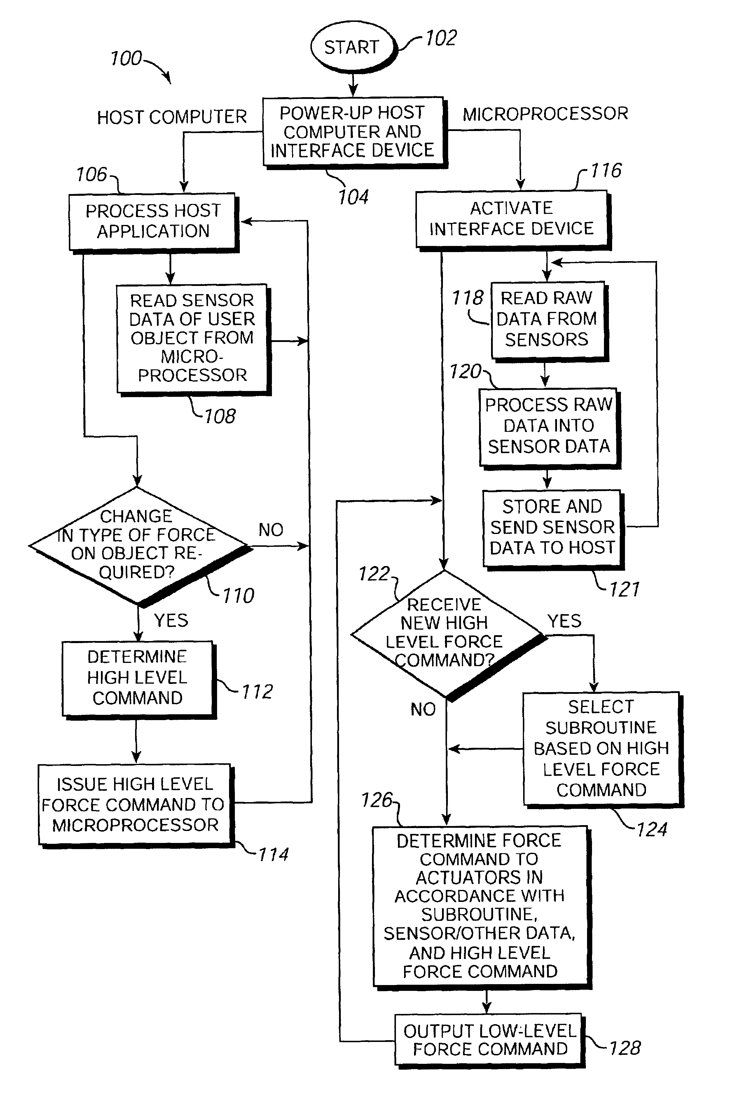
[0093]FIG. 5 is a flow diagram illustrating a method 100 for controlling force feedback interface device 14 of the present invention. Method 100 is directed to a “reflex” embodiment, in which host computer system 12 provides only high-level supervisory force commands to microprocessor 26, while the microprocessor independently determines and provides low-level force commands to actuators 30 as a “reflex” to control forces output by the actuators.

[0094]The process begins at 102. In step 104, host computer system 12 and interface device 14 are powered up, for example, by a user activating power switches. After step 104, the process 100 branches into two parallel processes. One process is implemented on host computer system 12, and the other process is implemented on local microprocessor 26.

[0095]In the host computer system process, step 106 is first implemented, in which an application program is processed. This application can be a simulation, video game, scientific program, or other...


PUM


Abstract

A method and apparatus for controlling and providing force feedback using an interface device manipulated by a user. A microprocessor is provided local to the interface device and reads sensor data from sensors that describes the position and/or other information about an object grasped and moved by the user, such as a joystick. The microprocessor provides the sensor data to a host computer that is coupled to the interface device by a communication bus that preferably includes a serial interface. In a “host-controlled” embodiment, the host computer calculates force values using the sensor data and other parameters of a host application program and sends the force values to the local microprocessor, which directly provides the force values to actuators to apply forces to the user object. In a “reflex” embodiment, the host computer sends high level supervisory commands to the local microprocessor, and the microprocessor independently implements a local process based on the high level command for reading sensor data and providing force values to the actuators using sensor data and other parameters.

Description

CROSS REFERENCE TO RELATED APPLICATIONS[0001]This application is a continuation of U.S. application Ser. No. 09 / 057,997, filed Apr. 9, 1998 now U.S. Pat. No. 6,300,937 which is a continuation of U.S. application Ser. No. 08 / 534,791, now U.S. Pat. No. 5,739,811, filed Sep. 27, 1995, which is 1) a continuation-in-part of application Ser. No. 08 / 489,068, now U.S. Pat. No. 5,721,566, filed Jun. 9, 1995, and 2) a continuation-in-part of application Ser. No. 08 / 461,170, now U.S. Pat. No. 5,576,727, filed June 6, 1995 which is a file wrapper continuation of application Ser. No. 08 / 092,974, filed July 16, 1993, now Abn. and all of which are incorporated herein by reference in their entireties.BACKGROUND OF THE INVENTION[0002]The present invention relates generally to interface devices between humans and computers, and more particularly to computer interface devices that provide force feedback to the user.[0003]Computer systems are used extensively in many different industries to implement c...

Claims


Application Information

Patent Timeline
IPC IPC(8): G06F3/033A63F13/06B25J9/16G01B5/008G01B7/004G01B21/04G05B19/42G05D25/02G05G9/047G06F3/00G06F3/01G06F3/038
CPCA63F13/06B25J9/1692G01B5/008G01B7/004G01B21/04G05B19/4207G05D25/02G05G9/047G06F3/011G06F3/016G06F3/0346G06F3/03545G06F3/038G06F3/0383H01H2003/008A63F2300/1037G05G2009/04766G05G2009/04777G06F2203/015A63F2300/1025A63F13/285
Inventor ROSENBERG, LOUIS B.
Owner IMMERSION CORPORATION
Why Eureka
Try Eureka