High performance resonant element

a resonant element and high-performance technology, applied in the field of high-performance resonant elements, can solve the problems of restricting the frequency content of the signal that can be transmitted, stub vias are generally unavoidable, and stub vias are conventionally viewed as having very adverse effects upon signal propagation, so as to achieve low loss, low overall cost, and high-performance resonant

Inactive Publication Date: 2007-12-13
GLOBALFOUNDRIES INC
View PDF7 Cites 1 Cited by
  • Summary
  • Abstract
  • Description
  • Claims
  • Application Information

AI Technical Summary

Benefits of technology

[0021]An exemplary embodiment of the present invention provides a via that may act as a relatively high performance resonant element that may be advantageously used for a large number of applications.
[0022]Conventionally, the characteristics of these vias may be selected such that losses are minimized. In stark contrast, in accordance with the present invention an exemplary embodiment takes advantage of the characteristics of a via by relying upon the via to process a signal. Since the incremental costs of vias in circuit boards are small, there is little impact to the overall cost of the finished assembly. The signal processing afforded by these structures may be adequate to allow dedicated components to be entirely replaced with significant cost savings.

Problems solved by technology

However, a stub via is generally unavoidable because of manufacturing cost constraints.
Stub vias are conventionally viewed as having very adverse effects upon signal propagation.
If it is not feasible to do so then, the signal impairments introduced by the stub vias may restrict the frequency content of the signal that can be transmitted.
This often leads to a reduction in the signal bandwidth that the connection can support.
Such effects may be particularly disadvantageous to a sinusoidal signal, and if the transit time, down and back from the end of the stub via is substantially equal to one-half of the period of the sinusoidal signal, then phase cancellation of the signal may completely attenuate the signal received from the input signal line 212.
This is a much more expensive process than drilling the holes after laminating the entire circuit board.
However, a blind via also suffers from higher fabrication costs, and due to processing limitations, usually can only access layers close to one of the circuit board surfaces.

Method used


Image

  • High performance resonant element
  • High performance resonant element
  • High performance resonant element

Examples


Embodiment Construction

[0036]Referring now to the drawings, and more particularly to FIGS. 1-9, there are shown exemplary embodiments of the methods and systems of the present invention.

[0037]Stub vias may be classified into two types: an open stub via and a shorted stub via. An open stub via has an end, which is distally located with respect to associated signal lines and which is not connected to any other conductor. In contrast, a shorted stub via has an end, which is distally located with respect to the associated signal lines, and which is connected to a ground.

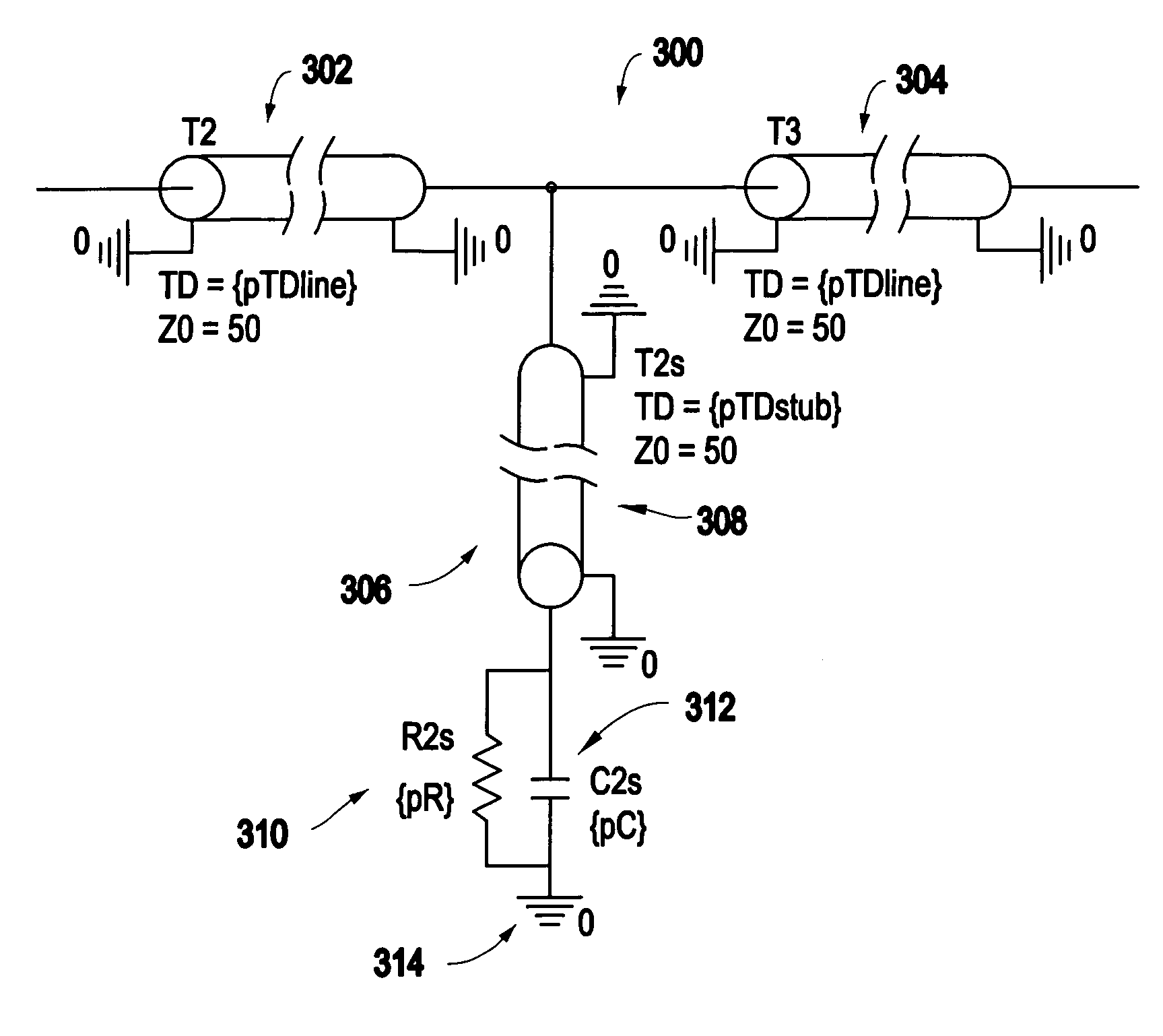
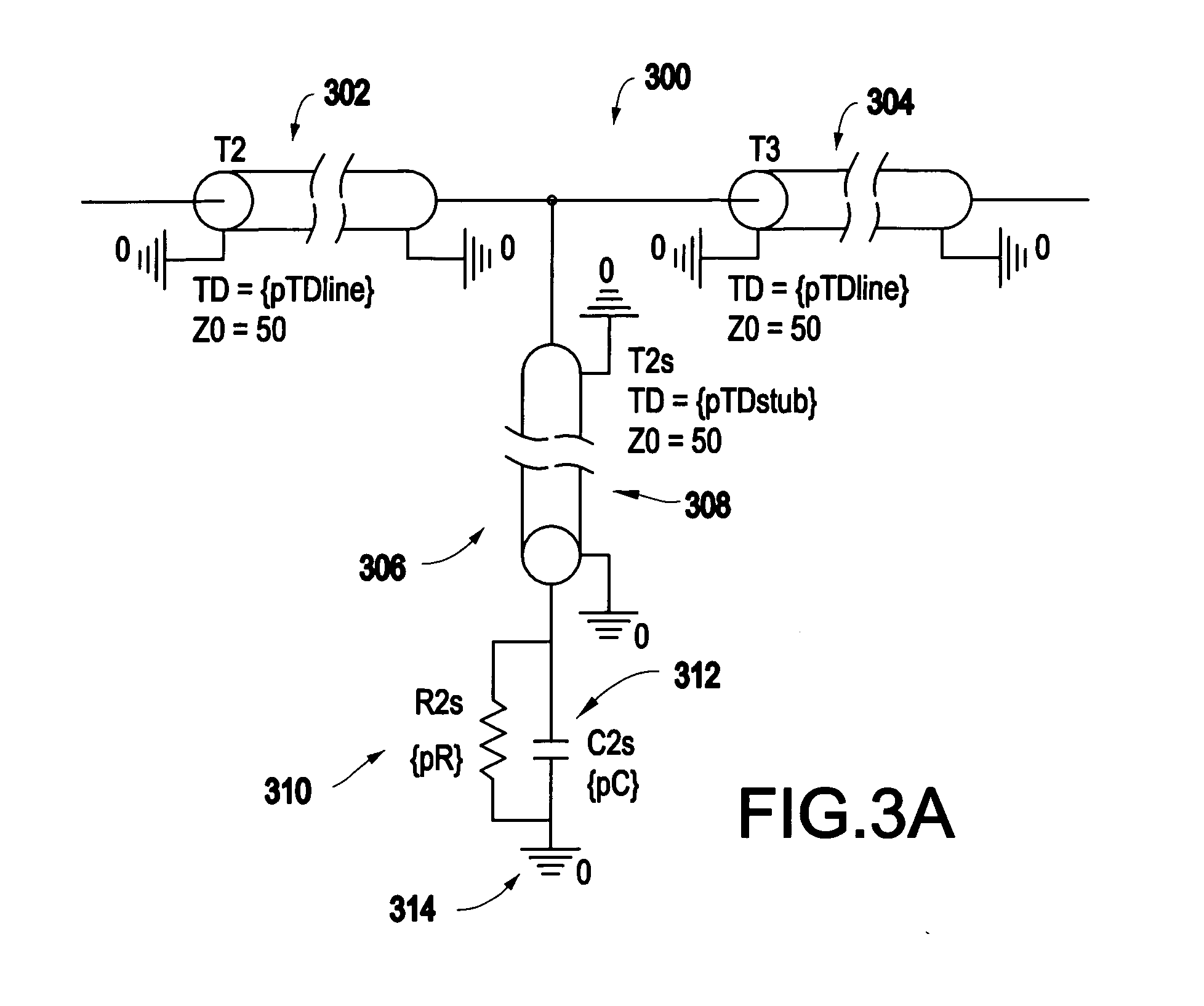
[0038]Propagation of a signal within a via segment, is often modeled as a propagation down a transmission line, which, in general possesses a different impedance from “real” signal lines. FIG. 3A illustrates a model 300 for a shorted-type via, and FIG. 3B illustrates a plot of a frequency response of the model of FIG. 3A.

[0039]The model 300 includes an input signal line 302, an output signal line 304, and a shorted-type via 306. The via portio...


PUM


Abstract

A circuit includes an input signal line, a high performance resonant element connected to the input signal line, and an output signal line connected to the high performance resonant element. The high performance resonant element is a via.

Description

[0001]This invention was made with Government support under Contract No.: H98230-04-C-0920 awarded by the National Security Agency. The Government has certain rights in this invention.BACKGROUND OF THE INVENTION[0002]1. Field of the Invention[0003]The present invention generally relates to a high performance resonant element. In particular, the present invention relates to methods and systems for processing a signal using a high performance resonant via.[0004]2. Description of the Related Art[0005]Signal lines and vias are both ubiquitous in circuit board and chip package technology. A signal line is capable of transmitting a broadband signal with high fidelity, while a via is necessary to connect signal lines that may reside on different levels within a laminated circuit board or to bring a signal from a signal line embedded between layers of a circuit board to the surface of the circuit board.[0006]A via may be formed by drilling a hole completely through a circuit board and then ...

Claims


Application Information

Patent Timeline
Patent Type & Authority Applications(United States)
IPC IPC(8): H04B14/04
CPCH04B3/14
Inventor GAUCHER, BRIAN P.KWARK, YOUNG HOONSCHUSTER, CHRISTIAN
Owner GLOBALFOUNDRIES INC
Why Eureka
Try Eureka