Head wrap procedure

Inactive Publication Date: 2013-07-23
INT BUSINESS MASCH CORP
View PDF3 Cites 5 Cited by
  • Summary
  • Abstract
  • Description
  • Claims
  • Application Information

AI Technical Summary

Problems solved by technology

However, the development of higher performance tape drive systems has created various problems in the design and manufacture of a tape head assembly for use in such systems.

Method used


Image

  • Head wrap procedure
  • Head wrap procedure
  • Head wrap procedure

Examples


embodiment 400

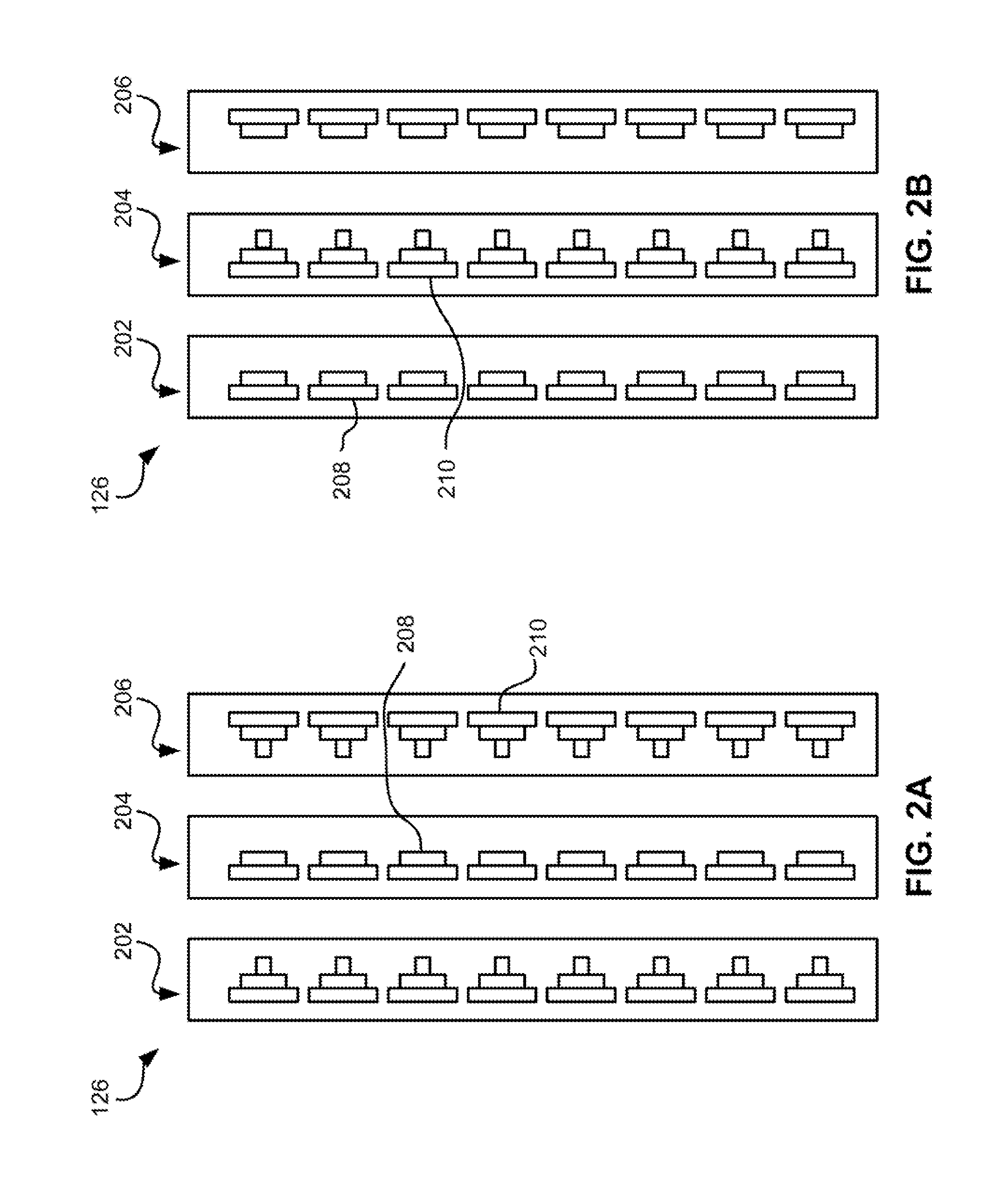
[0046]Depending on tape tension and stiffness, it may be desirable to angle the tape bearing surfaces of the outer modules relative to the tape bearing surface of the second module. FIG. 4 illustrates an embodiment 400 where the modules 302, 304, 306 are in a tangent (angled) configuration. Particularly, the tape bearing surfaces of the outer modules 302, 306 are about parallel to the tape at the desired wrap angle α2 of the second module 304. In other words, the planes of the tape bearing surfaces 308, 312 of the outer modules 302, 306 are oriented at about the desired wrap angle α2 of the tape 315 relative to the second module 304. The inventor has found that the tape will also pop off of the trailing module 306 in this embodiment, thereby reducing wear on the elements in the trailing module 306. These embodiments are particularly adapted for write-read-write applications. Additional aspects of these embodiments are similar to those given above.

embodiment 500

[0047]FIG. 5 illustrates an embodiment 500 where the modules 302, 304, 306 are in an overwrap configuration. Particularly, the tape bearing surfaces 308, 312 of the outer modules 302, 306 are angled slightly more than the tape 315 when set at the desired wrap angle α2 relative to the second module 304. In this embodiment, the tape does not pop off of the trailing module, allowing it to be used for writing or reading. Accordingly, the leading and middle modules can both perform reading and / or writing functions while the trailing module can read any just-written data. Thus, these embodiments are preferred for write-read-write, read-write-read, and write-write-read applications. In the latter embodiments, closures should be wider than the tape canopies for ensuring read capability. The wider closures will force a wider gap-to-gap separation. Therefore the preferred embodiment has a write-read-write configuration, which may use shortened closures that thus allow closer gap-to-gap separa...

embodiment 600

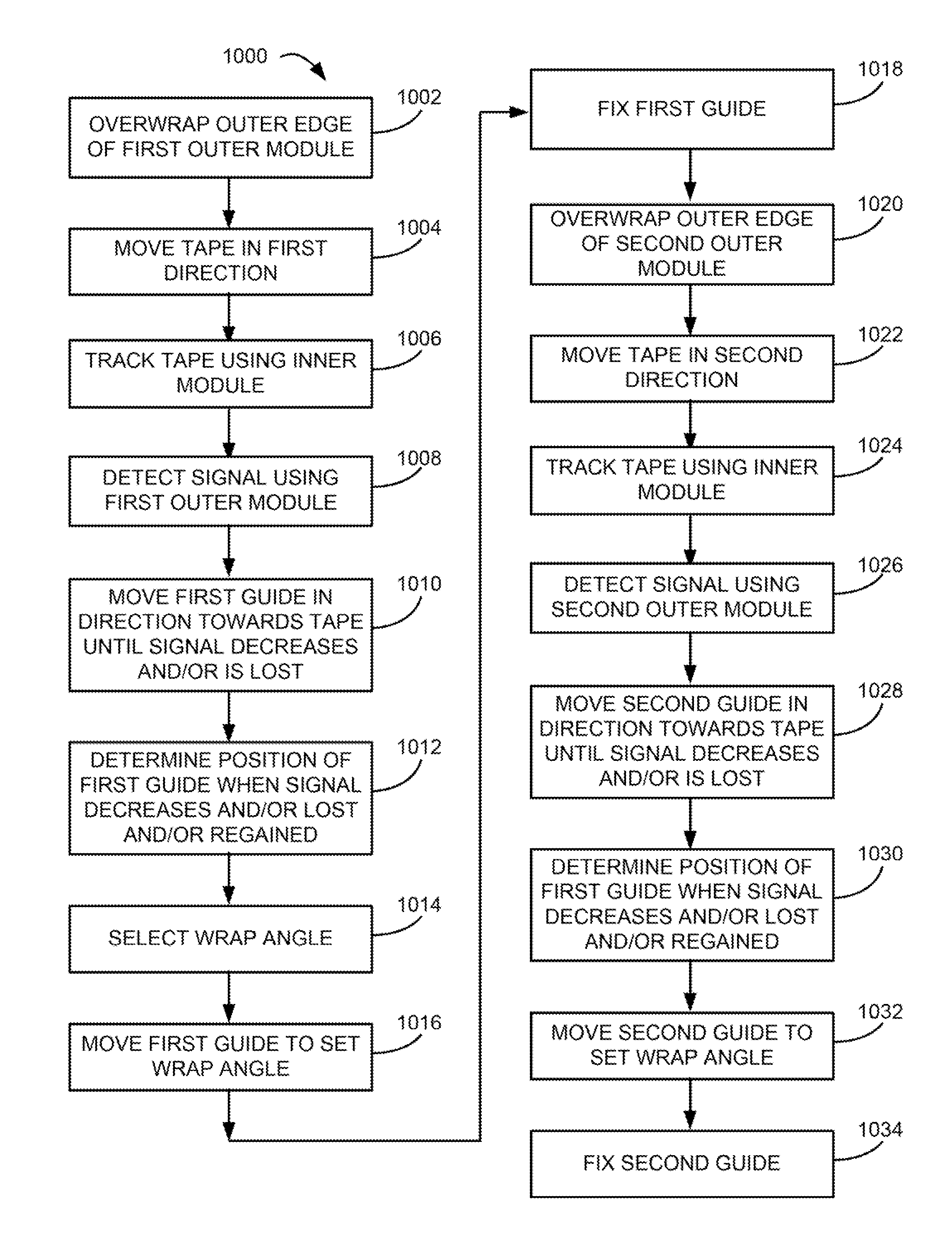
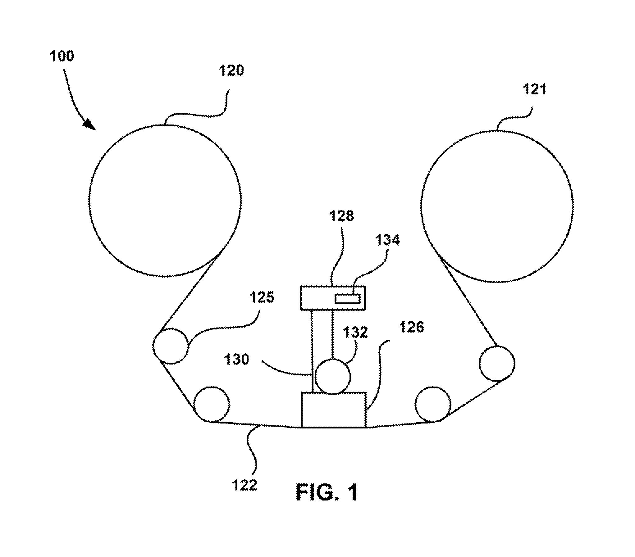
[0054]Referring to the embodiment 600 of FIG. 6-9, which may include a head as in any of FIGS. 1-5, the outer wrap angles α1 may be set in the drive, such as by guides 602, 604 of any type known in the art, such as adjustable rollers, slides, etc. For example, rollers having an offset axis may be used to set the wrap angles. The offset axis creates an orbital arc of rotation, allowing precise alignment of the wrap angle α1.

[0055]The outer wrap angles α1 and tolerances are typically on the order of about 0.5 to about 2 degrees, e.g., 1 degree with + / −0.1 degree tolerance. To establish this type of precision, the signals such as servo signals coming from the head while tape is moving across it, may be used to detect and monitor the tape to head wrap established during the drive manufacturing procedures.

[0056]In some approaches, the position of the guides may be set during manufacture and fixed, while in others the guides may be adjusted in the field, while in yet others, the guides ma...


PUM

PropertyMeasurementUnit
wrap angleaaaaaaaaaa
thicknessaaaaaaaaaa
thicknessaaaaaaaaaa

Abstract

According to one embodiment, a method includes tracking a magnetic tape moving in a first direction using at least one reader of an inner module of a head having at least the inner module and first and second outer modules positioned on opposite sides of the inner module and aligned with the inner module in a tape travel direction, detecting a signal using at least one reader of the first outer module as the tape passes thereacross, moving a guide positioned in front of the first outer module in a direction towards the tape until the signal detected by the first outer module decreases by a predetermined amount, and moving the guide directionally away from the tape to a position to set about a predetermined wrap angle of the tape relative to the first outer module after the signal detected by the first outer module decreases by the predetermined amount.

Description

BACKGROUND[0001]The present invention relates to magnetic tape storage systems, and more specifically, this invention relates to methods for wrapping a multi-module head.[0002]Business, science and entertainment applications depend upon computers to process and record data, often with large volumes of the data being stored or transferred to nonvolatile storage media, such as magnetic discs, magnetic tape cartridges, optical disk cartridges, floppy diskettes, or floptical diskettes. Typically, magnetic tape is the most economical and convenient means of storing or archiving the data. Storage technology is continually pushed to increase storage capacity and storage reliability. Improvement in data storage densities in magnetic storage media, for example, has resulted from improved medium materials, improved magnetic read / write heads, improved error correction techniques and decreased areal bit sizes. The data capacity of half-inch magnetic tape, for example, is now measured in thousan...

Claims


Application Information

Patent Timeline
Patent Type & Authority Patents(United States)
IPC IPC(8): G11B15/18
CPCG11B5/00826G11B15/62G11B5/60
Inventor BUI, NHAN X.GALE, ERNEST S.HANCOCK, REED A.TSURUTA, KAZUHIRO
Owner INT BUSINESS MASCH CORP
Why Eureka
Try Eureka