

Compound turbocharger system having a connectable compressor
a compressor and turbocharger technology, applied in the direction of combustion engines, hot gas positive displacement engine plants, machines/engines, etc., can solve the problems of performance loss in the context, dynamic behavior of such a system is thus subject to limitations, and the supercharging device of internal combustion engine presents certain problems
- Summary
- Abstract
- Description
- Claims
- Application Information
AI Technical Summary
Benefits of technology
Problems solved by technology
Method used
Image

Examples
Embodiment Construction
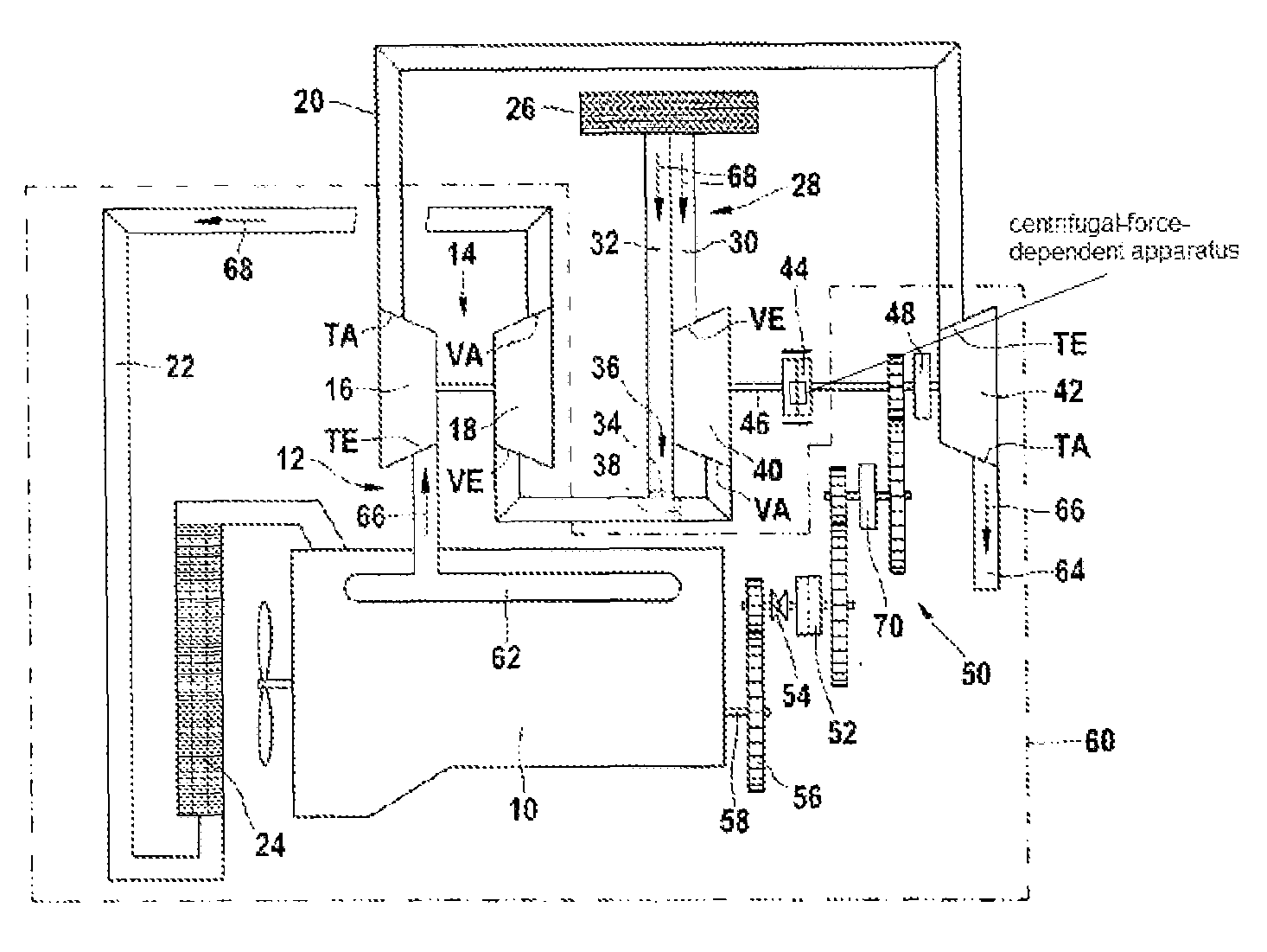
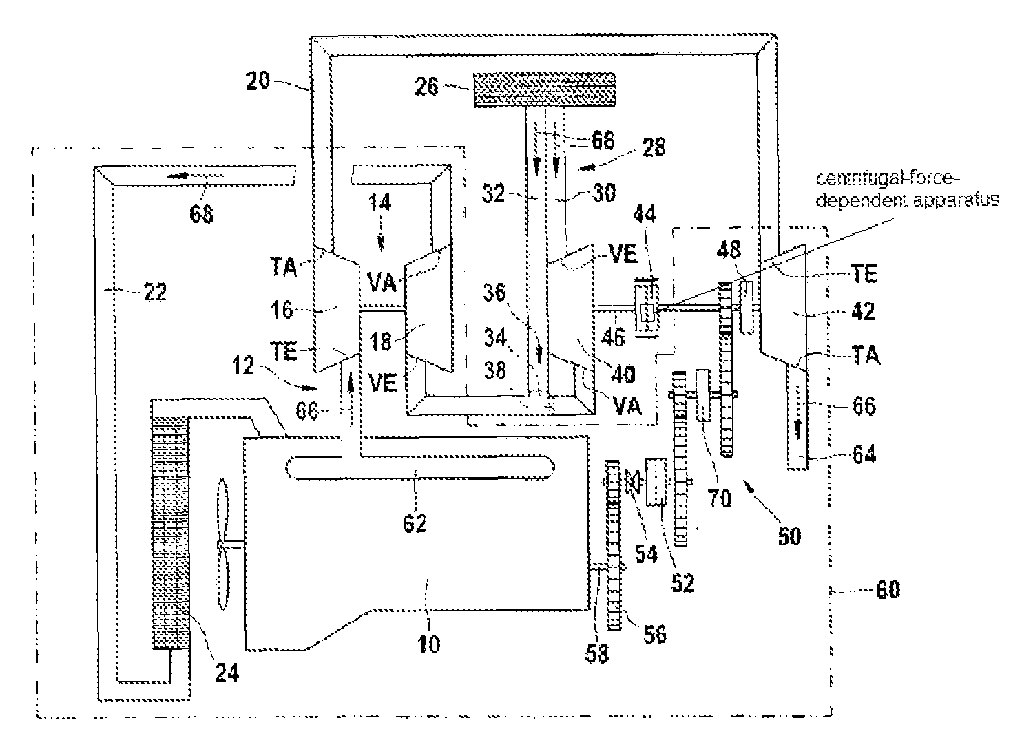
[0007]In accordance with the approach to achieving the object proposed according to the present invention, the combination of a turbocompound system and having a connectable additional flow compressor that is disposed on the same shaft as the power turbine, is proposed. In addition to an exhaust-gas turbocharger disposed in the exhaust section of an internal combustion engine, the internal combustion engine is therefore followed by a connectable compressor on the fresh-air side, and on the exhaust-gas side the already existing exhaust-gas turbocharger is followed by a power turbine. The above-described combination thus has the following properties: As a result of the coupling of the additional compressor with the crankshaft of the internal combustion engine, boost pressure is generated regardless of the availability of exhaust-gas energy, which leads to considerable torque increases at low engine speeds and thus substantially improves the initial-movement behavior that can be achiev...
PUM
 Abstract
Description
Claims
Application Information