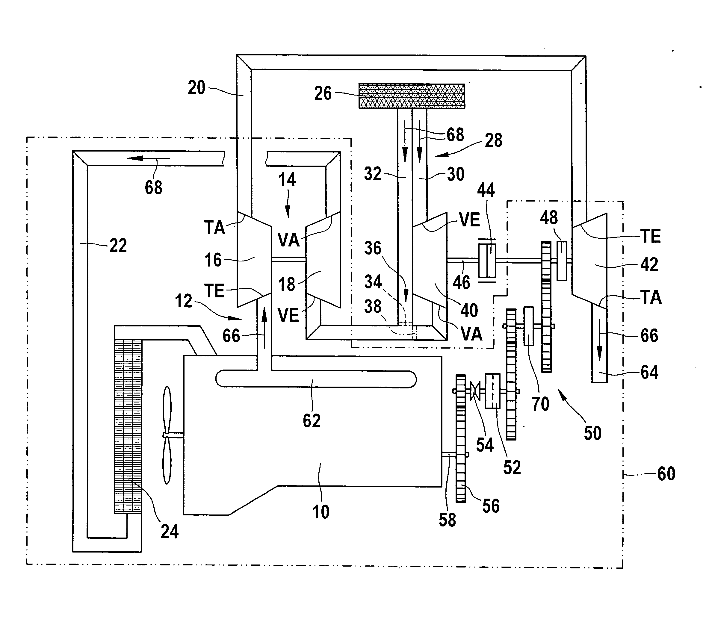
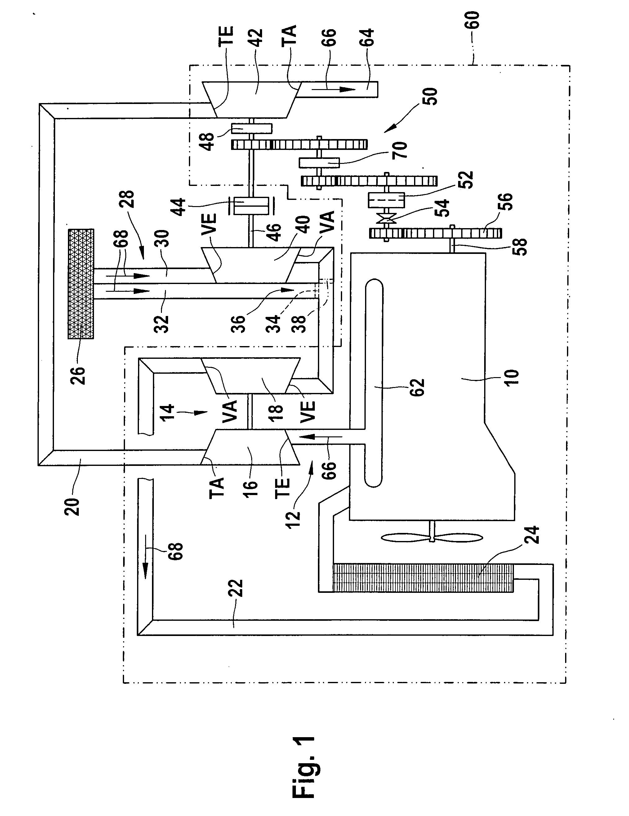
[0007]In accordance with the approach to achieving the object proposed according to the present invention, the combination of a turbocompound system and having a connectable additional flow compressor that is disposed on the same shaft as the power turbine, is proposed. In addition to an exhaust-gas
turbocharger disposed in the exhaust section of an internal combustion engine, the internal combustion engine is therefore followed by a connectable compressor on the fresh-air side, and on the exhaust-gas side the already existing exhaust-gas turbocharger is followed by a power turbine. The above-described combination thus has the following properties: As a result of the
coupling of the additional compressor with the
crankshaft of the internal combustion engine, boost pressure is generated regardless of the availability of exhaust-gas energy, which leads to considerable torque increases at low engine speeds and thus substantially improves the initial-movement behavior that can be achieved with the above-described combination. Because of the elevated engine output in the low-rotation-speed range of the internal combustion engine, the exhaust-gas turbocharger also begins to act very early on and then constitutes, together with the additional compressor, a two-stage supercharging system with high achievable excess air values, thereby making it easier to comply with emission limits. In addition to the exhaust-gas turbocharger driven by the exhaust-gas energy of the internal combustion engine, compliance with Euro 5 standard limits for commercial vehicles can be, assured, without performance losses, by way of the two-stage supercharging, i.e. operation of the additional compressor by the power turbine, despite the high exhaust recirculation rates that result.
[0009]What is characteristic of the proposed approach is an air section that enables parallel air flows and extends out from the
air filter toward the additional connectable compressor, and through which an additional
air volume can be conveyed. The connectable compressor works, via a controllable
clutch embodied mechanically, electrically, or hydraulically, on the same shaft that is associated with additional second power turbine of the turbocompound, thus yielding (when the
clutch is closed) a second exhaust-gas turbocharger; in other words, two-stage supercharging of the internal combustion engine is thereby implemented. The additional second compressor can be driven on the one hand directly by the internal combustion engine. For that purpose, the connectable additional compressor is driven by the internal combustion engine via the reduction transmission and the
freewheel (which in this case is locked). In order to preclude abrupt acceleration of the connectable additional compressor, which would result in damage to the reduction transmission or to the compressor, an additional clutch is used that preferably is embodied controllably. This controllable clutch is disposed on the shaft between the additional compressor and the power turbine. In situations of rapid load changes, the additional compressor is started up as a function of the air demand and increases the delivery of
fresh air into the
combustion chamber of the internal combustion engine. Examples of situations of rapid load changes that might be mentioned are on the one hand initial movement, since especially in the case of commercial vehicles, large initial-movement torques must be achieved at the lowest possible engine speed in order to minimize the input of
waste heat into the clutch. A further subsidiary instance of a rapid load change exists, for example, after the internal combustion engine is started and the individual gear ratios have subsequently been shifted through, or in difficult
terrain with severe changes in load. To implement this, a nonreturn valve is necessary, which prevents pre-compressed
fresh air from escaping through the
air filter.
[0010]A further enhancement of response and of the efficiency of the proposed approach can be achieved by the fact that if using a
freewheel or a switchable clutch, in the event of acceleration of the internal combustion engine the power turbine can be disconnected and its
mass need not also be accelerated.
[0011]The turbocompound system of itself offers the possibility that the output power of the power turbine can both be delivered to the
crankshaft of the internal combustion engine, and also used to precompress
fresh air. The aforementioned two-stage supercharging that can be implemented in accordance with the proposed approach by way of a direct connection of the power turbine and the additional compressor allow on the one hand the requisite Euro 5 emission limits for commercial vehicles to be complied with without an exhaust-gas post-
treatment system and without significant performance losses. At low loads and high engine speeds, however, a conventional single-stage supercharging concept is entirely sufficient. This can be achieved, according to the proposed approach, by the fact that the clutch between the additional compressor and the power turbine is opened. If pure two-stage supercharging operation is desired, a decoupling of the power turbine can be accomplished via the
freewheel, by interrupting the connection between the power turbine and the reduction transmission or the internal combustion engine itself. If the clutch between the additional compressor and the power turbine is embodied clutch that can be hydraulically filled and emptied, the rotation speed of the additional compressor can be controlled as desired. This offers advantages in terms of controlling both the
engine braking output when the internal combustion engine is in braking mode, and the supercharging ratio or air ratio in engine mode. When the internal combustion engine is in braking mode, the additional compressor is driven directly by the internal combustion engine and thereby delivers more air into the combustion chambers of the internal combustion engine, thus promoting cooling of the components as well as an improvement in braking effect. In
engine braking systems, in braking mode air is usually aspirated by the internal combustion engine and compressed during the compression
stroke thereof. Once the work of compression has been performed, the
compressed air is expelled through a special valve, meaning that the compression work previously performed cannot be recovered, in the manner of a “
gas spring,” during subsequent expansion.

