Shutter mechanism of card reader and card reader thereby

a card reader and shutter mechanism technology, applied in the field of shutter mechanism of card reader and card reader thereby, can solve the problems of large bending force likely to act on the connection point between the swing arm and the shutter, inability to prevent the insertion of foreign materials, and large bending force to increase the size so as to improve the strength of the shutter mechanism, improve the strength required, and facilitate the mechanical structure

Inactive Publication Date: 2013-07-30
SANKYO SEIKI MFG CO LTD
View PDF18 Cites 9 Cited by
  • Summary
  • Abstract
  • Description
  • Claims
  • Application Information

AI Technical Summary

Benefits of technology

[0010]Thus, it is an object of the present invention to provide a shutter mechanism of a card reader and a card reader equipped with the shutter mechanism that enable improvement of the strength required for preventing insertion of foreign materials into the card reader, more than expected conventionally, with a simple mechanical structure.
[0022]As described above, the shutter mechanism of a card reader according to the present invention enables improvement of the strength required for preventing insertion of foreign materials, more than expected conventionally, with an easy mechanical structure. Furthermore, the card reader according to the present invention enables improvement of the strength of the shutter mechanism required for preventing insertion of foreign materials, more than expected conventionally, with an easy mechanical structure.

Problems solved by technology

Unfortunately, it is indispensable for the shutter mechanisms described in Patent Document 1 and Patent Document 2 to have a solenoid for opening / closing the card path so that those shutter mechanisms become larger as well as costly.
Therefore, a large bending force is likely to act on the connection point of the swing arm and the shutter plate.
Accordingly, without the base plate at the backside of the shutter plate, insertion of a foreign material may result in deforming the connection point of the swing arm and the shutter plate so that it may become impossible to prevent insertion of foreign materials.

Method used


Image

  • Shutter mechanism of card reader and card reader thereby
  • Shutter mechanism of card reader and card reader thereby
  • Shutter mechanism of card reader and card reader thereby

Examples


Embodiment Construction

[0031]It is to be understood that the figures and descriptions of the present invention have been simplified to illustrate elements that are relevant for a clear understanding of the present invention, while eliminating, for purposes of clarity, many other elements which are conventional in this art. Those of ordinary skill in the art will recognize that other elements are desirable for implementing the present invention. However, because such elements are well known in the art, and because they do not facilitate a better understanding of the present invention, a discussion of such elements is not provided herein.

[0032]The present invention will now be described in detail on the basis of exemplary embodiments.

[0033]Schematic Structure of Card Reader:

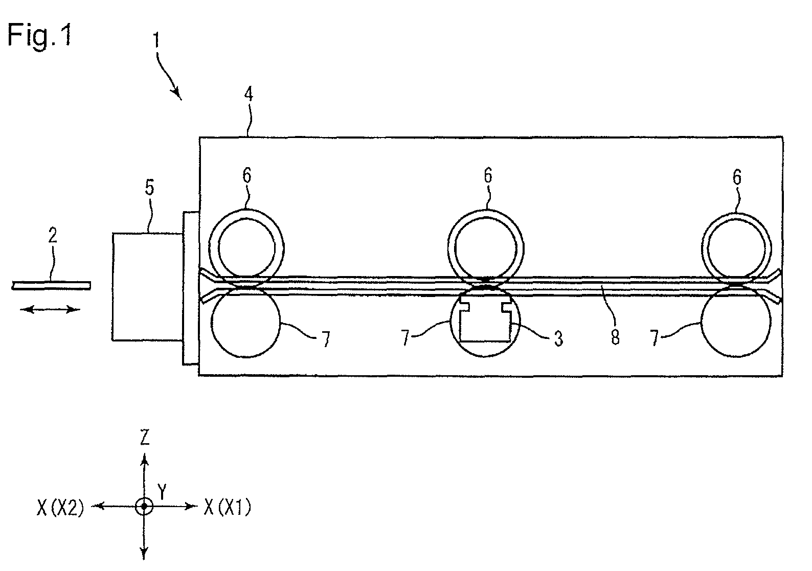
[0034]FIG. 1 is a drawing for explanation of a schematic structure of a card reader 1 in a side view according to an embodiment of the present invention.

[0035]The card reader 1 according to the embodiment reproduces information recorded ...


PUM


Abstract

A shutter mechanism of a card reader including a shutter part for opening / closing a card path through which a card is transferred. The shutter part includes: a closing part for closing the card path; a card contacting section, which contacts an end part of the card inserted into the card path, located at a further frontward position from the closing part in a direction X1; and shaft sections, having their rotation axis in a direction Y, for supporting the closing part and the card contacting section so as to keep them rotatable. The closing part and the shaft sections are located at their corresponding positions that are displaced from each other in a direction X. The closing part and the card contacting section rotate on the shaft sections to open the card path, when the end part of the card contacts with the card contacting section.

Description

[0001]The present application claims priority from PCT Patent Application No. PCT / JP2009 / 001400 filed on Mar. 27, 2009, which claims priority from Japanese Patent Application No. JP 2008-090100 filed on Mar. 31, 2008, the disclosure of which is incorporated herein by reference in its entirety.BACKGROUND OF THE INVENTION[0002]1. Field of the Invention[0003]The present invention relates to a shutter mechanism of a card reader for opening / closing a card path, through which a card is transferred, and a card reader equipped with the shutter mechanism.[0004]2. Description of Related Art[0005]Conventionally, a card insertion slot of a card reader for reproducing information recorded in a card and / or recording information into a card is equipped with a shutter mechanism for opening / closing a card path (For example, refer to Japanese Unexamined Patent Application Publication No. 2000-331125 (hereinafter “Patent Document 1”) and Japanese Unexamined Patent Application Publication No. H10-40344...

Claims


Application Information

Patent Timeline
Patent Type & Authority Patents(United States)
IPC IPC(8): G06K13/06G06K13/24G06K7/00G06K5/00G06K7/06G06K7/04
CPCG06K13/0875G06K13/0843
Inventor MIZAWA, MAMORU
Owner SANKYO SEIKI MFG CO LTD
Why Eureka
Try Eureka