Highly efficient impact operative arrowheads
a technology of arrowheads and arrowheads, applied in the field of mechanical expansion of arrowheads, can solve the problems of small diameter design and easy scalding of arrowheads, and achieve the effects of less manufacturing cost, simple design and easy maintenan
- Summary
- Abstract
- Description
- Claims
- Application Information
AI Technical Summary
Benefits of technology
Problems solved by technology
Method used
Image
Examples
embodiment 25
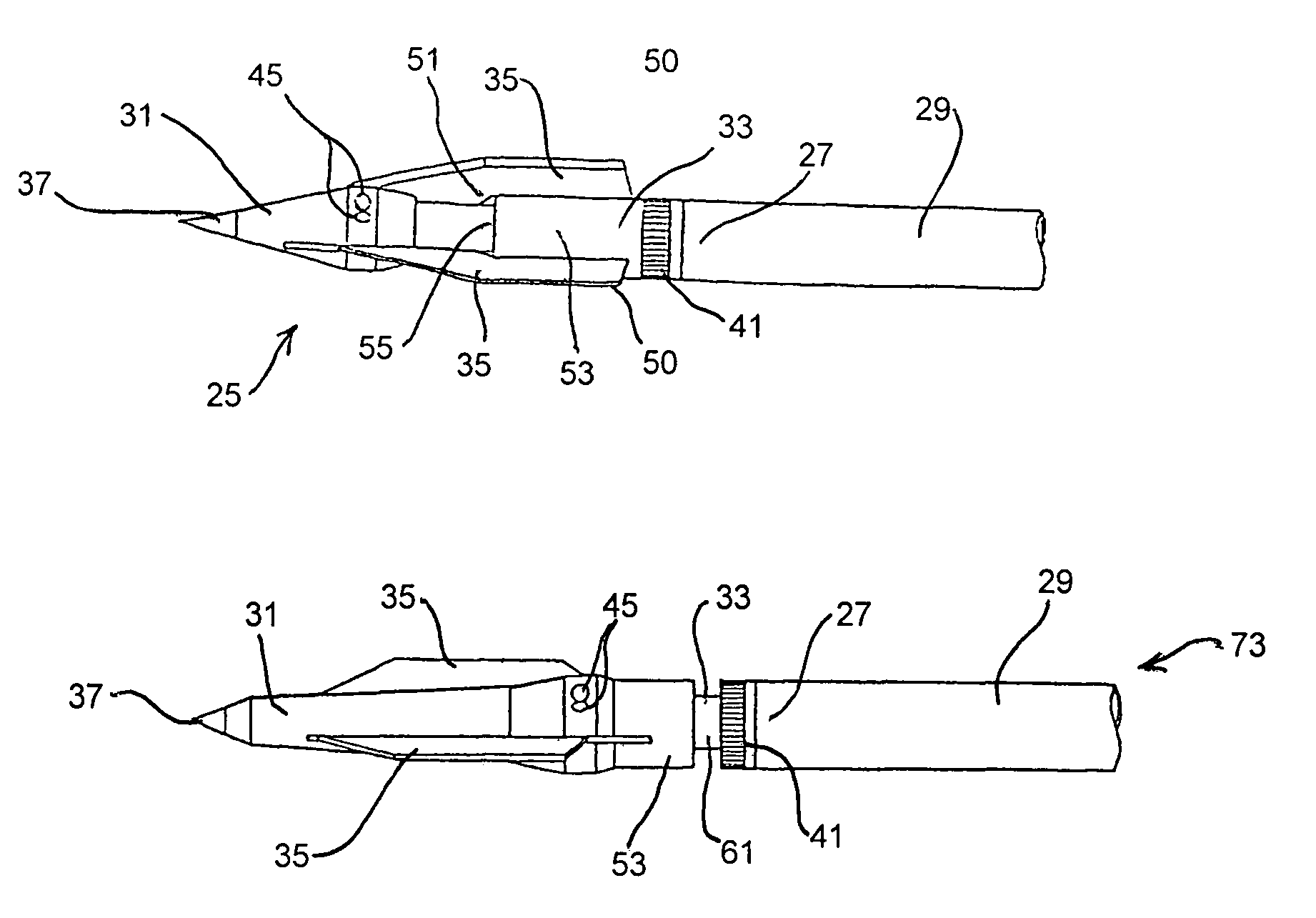
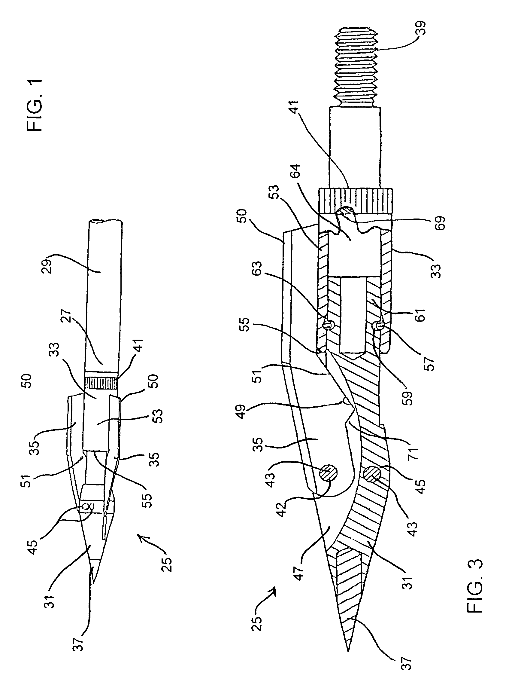
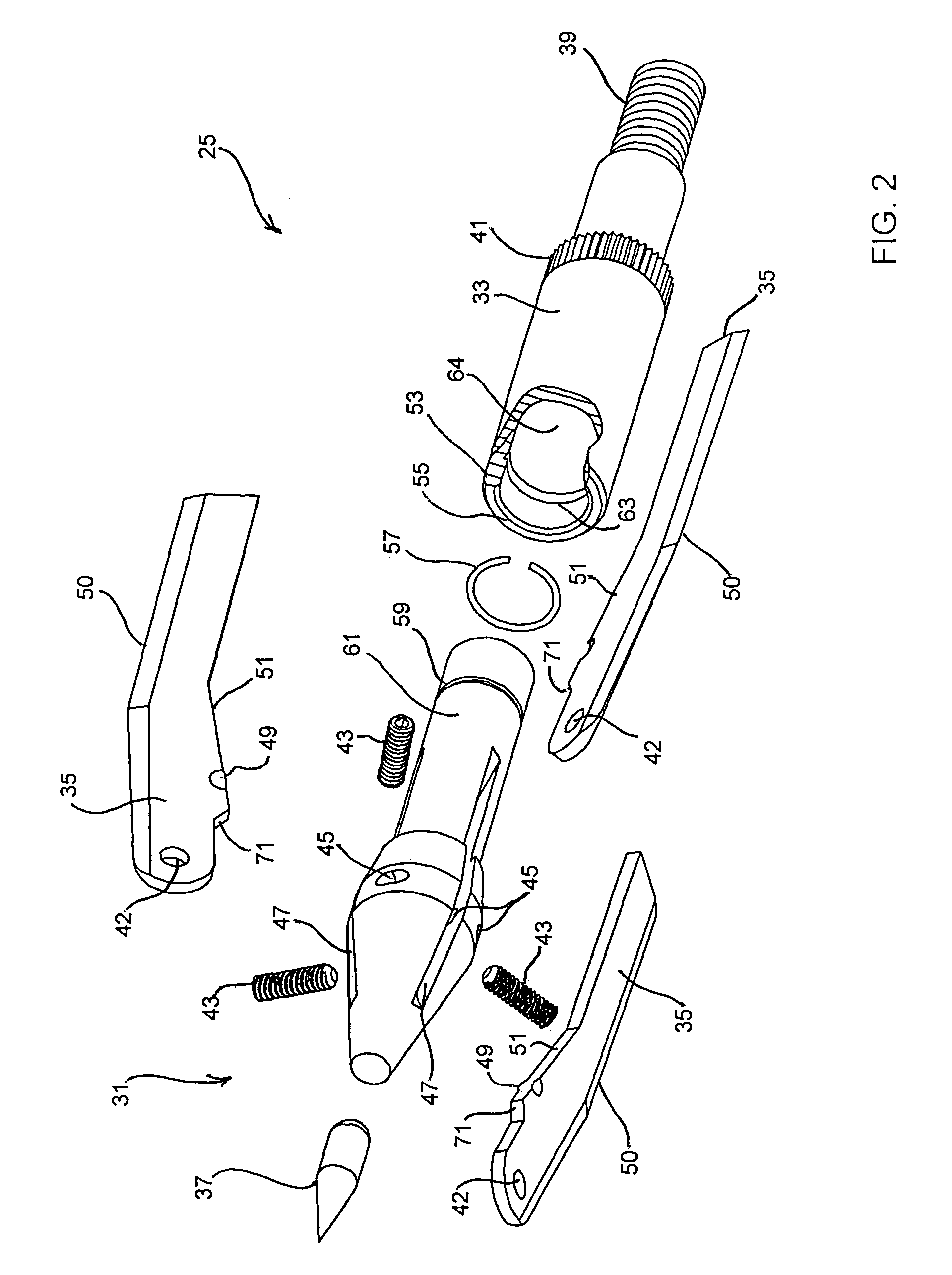
[0045]Embodiment 25 specifically shows rearward external blade actuation of a broadhead type blade configuration (pivoting towards the forward section of the arrowhead body relative to the direction of arrow travel with cutting edges 50 of blades 35 exposed outside of slots 47 in the armed position) and having tip 37 mounted in the leading end of the forward section of body 31. Actuator 33 includes cylinder portion 53 having a blade contacting end 55 in the nature of a cam sleeve, actuation contact surfaces 51 of blades 35 in the nature of cam followers and extending to a position outside of slots 47 when the blades are in the armed position. Spring ring 57 (preferably stainless steel) is mounted in retention seat 59 at an external surface of piston portion 61 of body 31 and is received in annular guide groove 63 defined at an axial internal surface of axial bore 64 of cylinder portion 53. In all embodiments it is preferable that depth of annular guide groove 63, at least at first g...
embodiment 73
[0049]Embodiment 73 specifically shows rearward internal blade activation of a flip-blade type blade configuration (pivoting towards the rearward section of the arrowhead body relative to the direction of arrow travel with cutting edges 50 of blades 35 located within slots 47 in the armed position). Actuation contact surfaces 51 of blades 35 in this embodiment are located entirely internal to body 31. Spring ring 57 is mounted in retention seat 59 at an external surface of piston portion 61 and is received in annular guide groove 63 defined at an axial internal surface of axial bore 64 of cylinder portion 53.
[0050]In embodiment 73 guide groove 63 is a tapered groove much as previously described with regard to embodiment 25 except that assembly retention is maintained solely by guide groove end 65 (forming a positive stop to rearward ring travel thereat). As shown in FIGS. 7 and 8, guide groove 63 is located so that, upon target impact, blade contacting end 55 of striker pin 75 of ac...
embodiment 83
[0054]Embodiment 83 specifically shows forward internal blade activation of a flip-blade type blade configuration (pivoting towards the rearward section of the arrowhead body relative to the direction of arrow travel with cutting edges 50 of blades 35 located within slots 47 in the armed position). Actuation contact surfaces 51 at striker notches 85 in this embodiment are located at honed edge 50 of blades 35. Spring ring 57 is mounted in retention seat 59 at an external surface of piston portion 61 and is received in annular guide groove 63 defined at an axial internal surface of axial bore 64 of cylinder portion 53.
[0055]Guide groove 63 is a tapered groove much as previously described with regard to the prior embodiments, assembly retention maintained by the positive stop of guide groove end 65. As shown in FIGS. 10 and 12, guide groove 63 is located so that, upon target impact at tip 37, blade contacting end 55 of piston 61 / actuator 33 comes into contact with actuation contact su...
PUM
 Abstract
Description
Claims
Application Information
 - R&D
- Intellectual Property
- Life Sciences
- Materials
- Tech Scout
- Unparalleled Data Quality
- Higher Quality Content
- 60% Fewer Hallucinations
Browse by: Latest US Patents, China's latest patents, Technical Efficacy Thesaurus, Application Domain, Technology Topic, Popular Technical Reports.
© 2025 PatSnap. All rights reserved.Legal|Privacy policy|Modern Slavery Act Transparency Statement|Sitemap|About US| Contact US: help@patsnap.com


