Inerting system for an aircraft

a technology of aircraft and inerting system, which is applied in the direction of energy-efficient board measures, transportation and packaging, and separation processes, etc. it can solve the problems of air enriched with oxygen being wasted, pressure level of air introduced into the inerting system, and inerting system, etc., to increase the oxygen concentration locally and reduce the effect of constructive expenditur

Active Publication Date: 2013-08-06
AIRBUS OPERATIONS GMBH
View PDF28 Cites 15 Cited by
  • Summary
  • Abstract
  • Description
  • Claims
  • Application Information

AI Technical Summary

Benefits of technology

[0016]An air processing system—that, for example, also performs a thermal process in an air cycle—may feature a number of lines, in which air with different pressures and temperatures is transported. It is possible to tap into the air flow transported in one or more of these lines such that an input air flow for the air separation module is obtained. This provides—depending on the air extraction point—the advantage that, for example, pre-conditioned air could be extracted from the air processing system such that the process of pre-conditioning the air introduced into the air separation module is already carried out by the air processing system. This would eliminate the need for corresponding devices in the inerting system such that the weight could be additionally reduced due to the elimination of said devices. It is possible to eliminate, in particular, a separate dehumidification, compression and decontamination in the inerting system itself. It is also preferred that a dehumidifying unit of the air processing system can either be switched on or avoided with the aid of a bypass depending on the flight phase and the specific properties of the ambient air associated therewith.
[0026]In a particularly preferred embodiment of the inerting system according to the invention, the first air flow enriched with oxygen is introduced into a mixing unit for mixing fresh air and recirculated cabin air and the first air outlet can be connected to the mixing unit for this purpose. Due to this measure, existing environmental control systems that usually already feature a mixing unit can be significantly enhanced with relatively low constructive expenditures.

Problems solved by technology

In the above-described systems known from the prior art, it is disadvantageous that either air enriched with oxygen is wasted by being discharged into the surroundings of the aircraft or the pressure level of the air introduced into an inerting system is so low that compressors need to be used for introducing air enriched with oxygen into the cabin.
It is furthermore disadvantageous that inerting systems according to the prior art feature elaborate devices for pre-conditioning bleed air that create additional costs and weight.

Method used


Image

  • Inerting system for an aircraft
  • Inerting system for an aircraft
  • Inerting system for an aircraft

Examples


Embodiment Construction

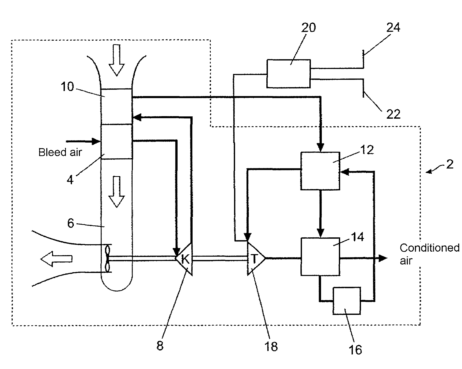
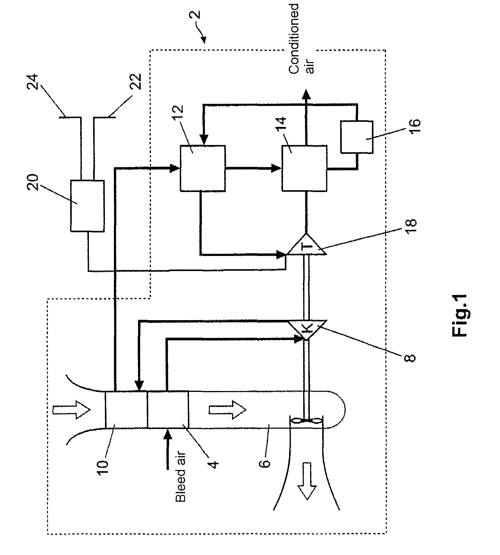
[0038]A first exemplary embodiment of the inerting system according to the invention is illustrated in FIG. 1. This figure shows an air processing system 2 that serves for processing bleed air from an engine in such a way that it can be used for air-conditioning a passenger cabin of an aircraft. The bleed air extracted from an intermediate pressure extraction point of an engine has, for example, a temperature of approximately 200° C. and a pressure of 3 bar. In the arrangement illustrated in FIG. 1, it flows through a primary heat exchanger 4 that is arranged in a ram-air duct 6. This causes the temperature of the bleed air to drop, for example, to approximately 100° C. The pressure, in contrast, only drops by a relatively small amount and still lies at approximately 2.9 bar downstream of the heat exchanger 4. A compressor 8 compresses the bleed air such that the pressure rises, for example, to 4.8 bar and the temperature increases to approximately 180° C. The compressed air ultimat...


PUM

PropertyMeasurementUnit
pressureaaaaaaaaaa
temperatureaaaaaaaaaa
pressureaaaaaaaaaa

Abstract

The invention pertains to an inerting system for an aircraft featuring at least one air separation module with at least one air inlet, a first air outlet and a second air outlet. The air separation module is designed for splitting an input air flow into a first air flow and a second air flow, wherein the first air flow is enriched with oxygen in comparison with the input air flow and discharged at the first air outlet and the second air flow is enriched with nitrogen in comparison with the input air flow and discharged at the second air outlet. In comparison with known inerting systems, the inerting system according to the invention is characterized in that the air inlet can be connected to an air extraction point in an air processing system and the inerting system is designed for routing the first air flow into a cabin to be air-conditioned.

Description

CROSS-REFERENCE TO RELATED APPLICATIONS[0001]This application is a national phase entry under 35 U.S.C. §371 of International Application No. PCT / EP2009 / 056180, filed May 20, 2009, published in German, which claims the benefit of the filing date of German Patent Application No. 10 2008 024 503.8, filed May 21, 2008 and U.S. Provisional Patent Application No. 61 / 128,385, filed May 21, 2008, the entire disclosures of which are hereby incorporated herein by reference.TECHNICAL FIELD[0002]The invention relates to an inerting system and an environmental control system for an aircraft for inerting a fuel tank.TECHNOLOGICAL BACKGROUND[0003]Due to the low outside temperatures and the low atmospheric pressure at high altitudes, environmental control systems are an indispensable component of modern commercial aircraft. Only the utilization of such systems makes it possible to transport passengers over greater distances. The architecture of environmental control systems is subject to a constan...

Claims


Application Information

Patent Timeline
Patent Type & Authority Patents(United States)
IPC IPC(8): B01D53/02B64D37/32
CPCB64D13/06B64D37/32B64D2013/0677Y02T50/44Y02T50/56Y02T50/40Y02T50/50
Inventor CREMERS, JOERGKRICKE, KLAUS-DIETERSCHUMACHER, CHRISTIAN
Owner AIRBUS OPERATIONS GMBH
Why Eureka
Try Eureka