Computer readable storage medium including effective light source calculation program, and exposure method

a computer-readable storage medium and light source technology, applied in the field of computer-readable storage medium including an effective light source calculation program, can solve the problems of method time and labor, and it takes an enormous amount of time to determine the effective light source, and achieve the effect of reducing the decrease in image formation performan

Inactive Publication Date: 2013-08-06
CANON KK
View PDF15 Cites 3 Cited by
  • Summary
  • Abstract
  • Description
  • Claims
  • Application Information

AI Technical Summary

Benefits of technology

[0006]The present invention calculates an effective light source within a short time without performing any time-consuming calculation of image formation. Furthermore, the present invention calculates an effective light source so as to reduce a decrease in image formation performance in a case including an aberration as compared with a case including no aberration.

Problems solved by technology

However, this method requires time and labor.
However, since this method must calculate many optical images (aerial images), it takes an enormous time to determine the effective light source.

Method used


Image

  • Computer readable storage medium including effective light source calculation program, and exposure method
  • Computer readable storage medium including effective light source calculation program, and exposure method
  • Computer readable storage medium including effective light source calculation program, and exposure method

Examples


first embodiment

[0048][First Embodiment]

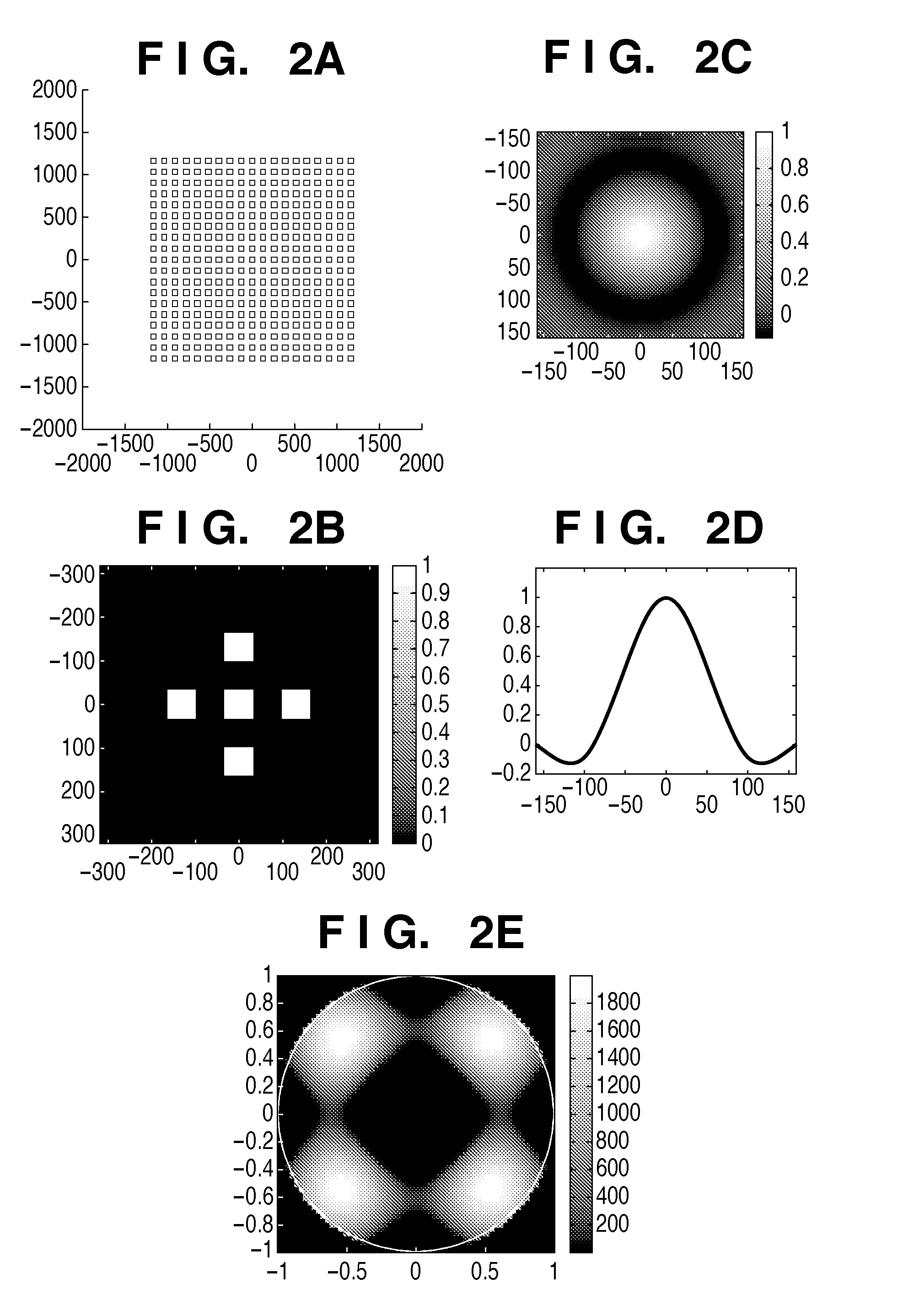
[0049]The first embodiment of a method of determining an effective light source will be explained below with reference to FIGS. 3A to 3F. FIG. 3A shows a target pattern to be formed on a substrate. Assume that the minimum half pitch HP of the target pattern is 65 (nm). When normalized by exposure light wavelength λ=193 (nm) and NA=1.35, the target pattern half pitch is k1=0.45. A mask was assumed to be a halftone phase-shift mask, the transmittance of the pattern was 100%, and that of the periphery of the pattern was 6%. A phase difference between the pattern and the periphery of the pattern is π (rad). In the target pattern, dense holes and isolated holes are arranged in the lateral direction. The target pattern is not a simple periodic pattern but includes the isolated holes, and this makes it difficult to balance the sizes of the isolated holes and dense holes. The ordinate and abscissa of FIG. 3A showing the pattern are indicated by a length (nm) converte...

second embodiment

[0056][Second Embodiment]

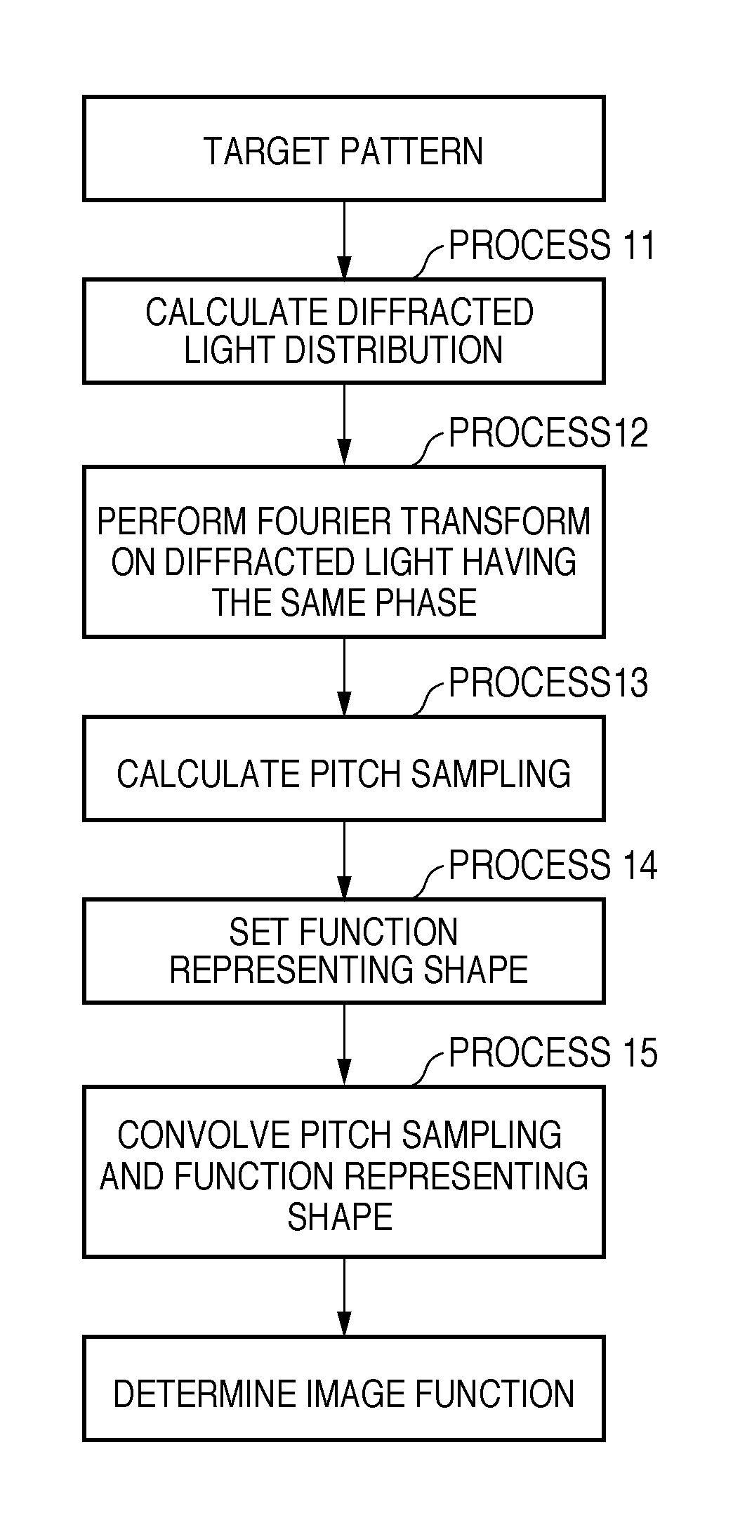
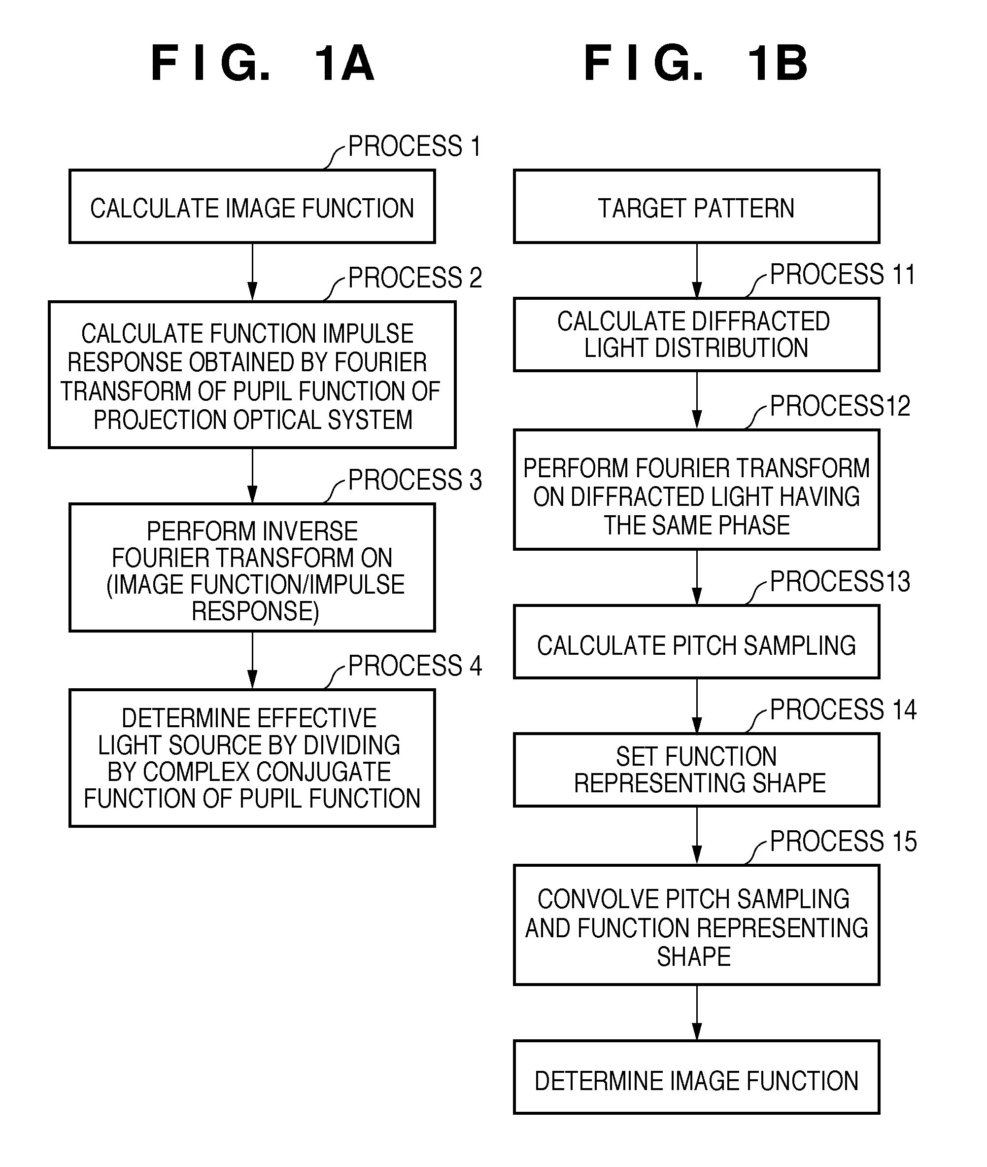
[0057]A method of determining an effective light source by using the same pattern example as in the first embodiment will be explained below. FIG. 5A shows a target pattern to be formed on a substrate. The minimum half pitch of the target pattern is HP=50 (nm). That is, since exposure light wavelength λ=193 (nm) and NA=1.35, the half pitch of the target pattern is k1=0.35. A mask was assumed to be a binary mask, the transmittance of the pattern was 1, and that of the periphery of the pattern was zero. FIGS. 5E and 5F illustrate an image function and effective light source derived by the second image function calculation method shown in FIG. 1B. FIG. 5E shows the image function, and FIG. 5F shows the effective light source.

[0058]The image function deriving method using the second calculation method will be explained in detail below. To obtain pitch sampling from the target pattern, a computer obtained the diffracted light distribution of the target pattern. F...

third embodiment

[0062][Third Embodiment]

[0063]A method of determining an effective light source by using an example of a brick wall pattern will be explained below. FIG. 7A shows a target pattern to be formed on a substrate. The half pitch of the target pattern in the lateral direction is HP=60 (nm). The half pitch of the target pattern in the lateral direction is HP=60 (nm). The pattern has a width of 60 (nm) and a length of 240 (nm). That is, since exposure light wavelength λ=193 (nm) and NA=1.35, the minimum half pitch of the target pattern is k1=0.42. A mask was assumed to be a binary mask, the transmittance of the pattern was 1, and that of the periphery of the pattern was zero.

[0064]In process 1, an image function was obtained by the second calculation method shown in FIG. 1B. In process 14 of FIG. 1B, as the function representing the shape of an element forming the target pattern, a function when the element shape was assumed to be an elliptic shape and a function when the element shape was ...


PUM

PropertyMeasurementUnit
wavelengthaaaaaaaaaa
lengthaaaaaaaaaa

Abstract

A storage medium includes a program which causes a computer to execute a method of calculating a light intensity distribution on a pupil plane of an illumination optical system. The method includes: determining an impulse response function of a projection optical system by performing Fourier transform on a pupil function of the projection optical system; setting a length to a second zero point of the impulse response function as a response length, extracting, from elements forming a target pattern, only elements inside am area within radius which is response length, and determining a function indicating the extracted pattern as an image function; and obtaining the light intensity distribution based on the pupil function, the determined impulse response function, and the determined image function.

Description

BACKGROUND OF THE INVENTION[0001]1. Field of the Invention[0002]The present invention relates to a computer readable storage medium including an effective light source calculation program, and an exposure method.[0003]2. Description of the Related Art[0004]An exposure apparatus has conventionally been used when manufacturing fine semiconductor devices such as semiconductor memories and logical circuits by using the photolithography technique. The exposure apparatus projects a pattern (circuit pattern) drawn on a mask (reticle) as an original onto a substrate such as a wafer by using a projection optical system, thereby transferring the pattern onto the substrate. Recently, the micropatterning techniques for semiconductor devices have advanced, and the exposure apparatus is required to form patterns having dimensions smaller than the exposure wavelength (the wavelength of exposure light). In the formation of fine patterns like these, the image quality is affected by the illumination ...

Claims


Application Information

Patent Timeline
Patent Type & Authority Patents(United States)
IPC IPC(8): G03B27/32G03B27/54G03B27/72G03F7/20
CPCG03F7/70083G03F7/70091G03F7/70508G03F7/705
Inventor KAWASHIMA, MIYOKOYAMAZOE, KENJIFUJISHIMA, HIRONOBU
Owner CANON KK
Why Eureka
Try Eureka