
Fuel efficiency measuring system for fuel cell vehicle

a fuel cell and fuel efficiency technology, applied in the direction of battery/fuel cell control arrangement, electric devices, instruments, etc., can solve the problems of fuel efficiency measurement system and method, inability to evaluate the efficiency of hydrogen fuel cell vehicles in which fuel cell stacks are mounted, and many parts, so as to reduce manufacturing costs, improve workability of the overall system, and save additional manufacturing costs

Active Publication Date: 2013-08-13
HYUNDAI MOTOR CO LTD
View PDF9 Cites 2 Cited by
  • Summary
  • Abstract
  • Description
  • Claims
  • Application Information

AI Technical Summary

Benefits of technology

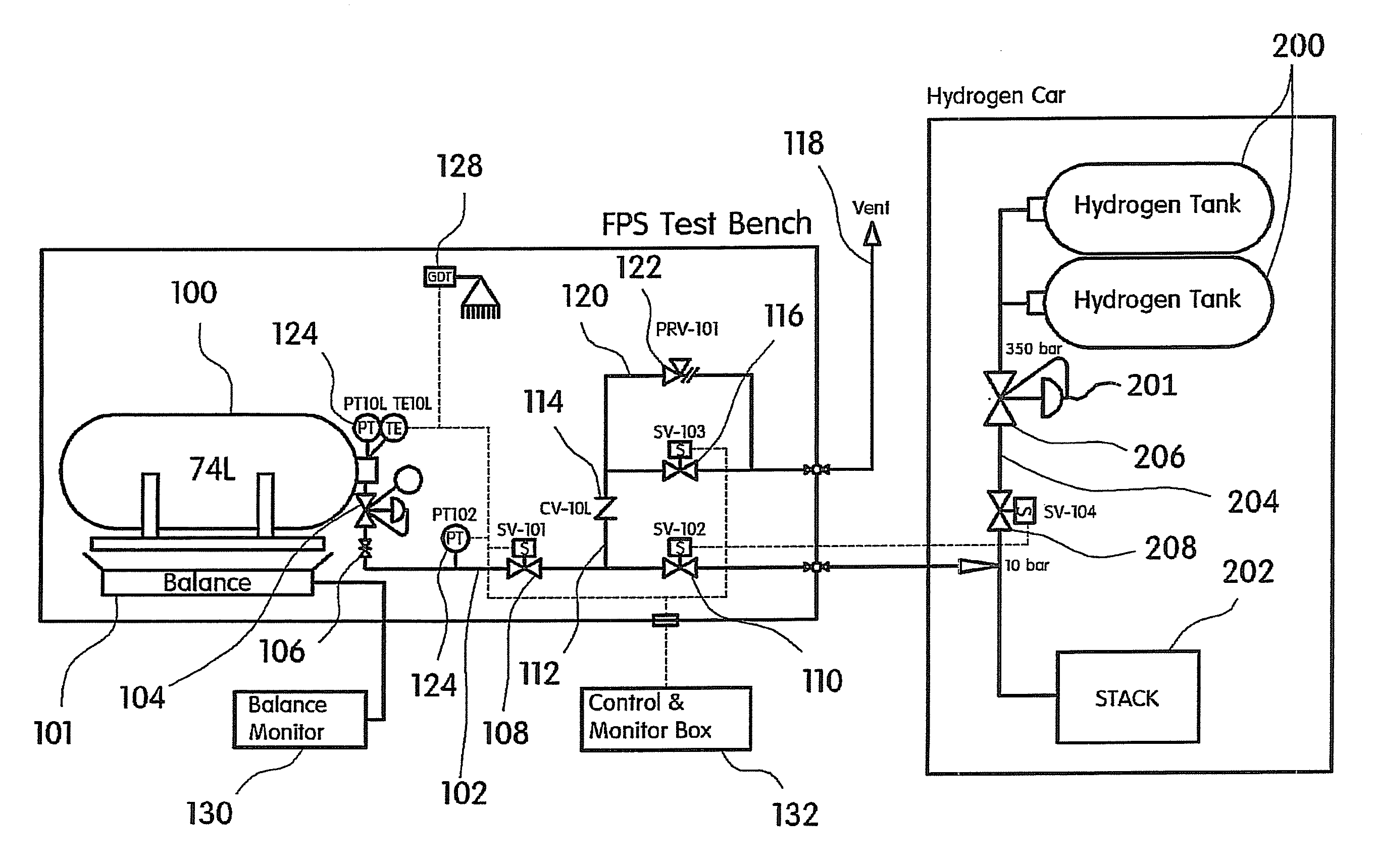
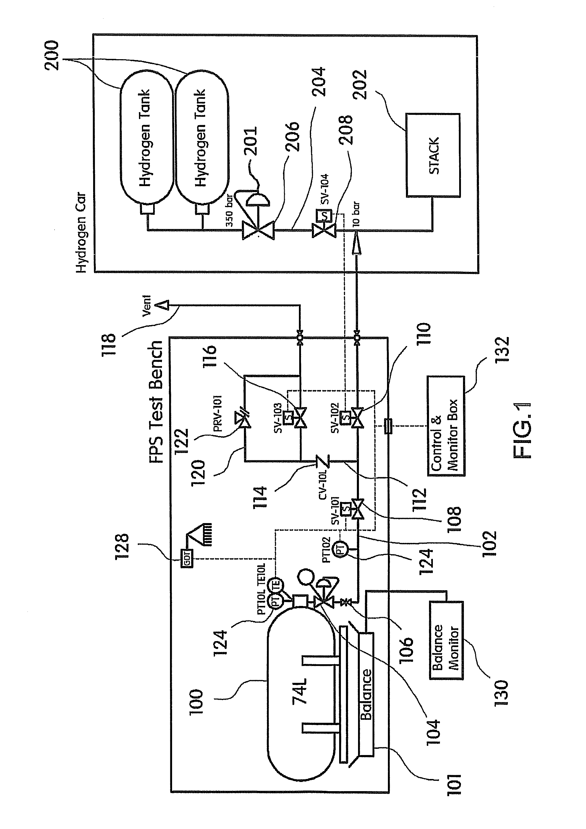
The present invention is about an improved system for measuring the fuel efficiency of fuel cell vehicles. This system eliminates the need for a high-cost break-away coupler that conventionally connects a fuel efficiency measuring unit to the vehicle. Instead, residual air in the hydrogen supply line is removed using a vehicle side hydrogen tank. This simplifies the installation process and reduces manufacturing costs. Additionally, a quick coupler can be easily separated when measuring the weight of the hydrogen tank. Overall, this invention reduces manufacturing costs and improves the efficiency of fuel cell vehicles.

Problems solved by technology

Those skilled in the art would realize that it is impossible to evaluate the efficiency of a hydrogen fuel cell vehicle in which a fuel cell stack is mounted using previous fuel consumption measuring methods which have been applied to general internal combustion engines, because typically these method measure the amount of carbons contained in exhaust.
However, this fuel efficiency measuring system and method suffers from a number of disadvantages.
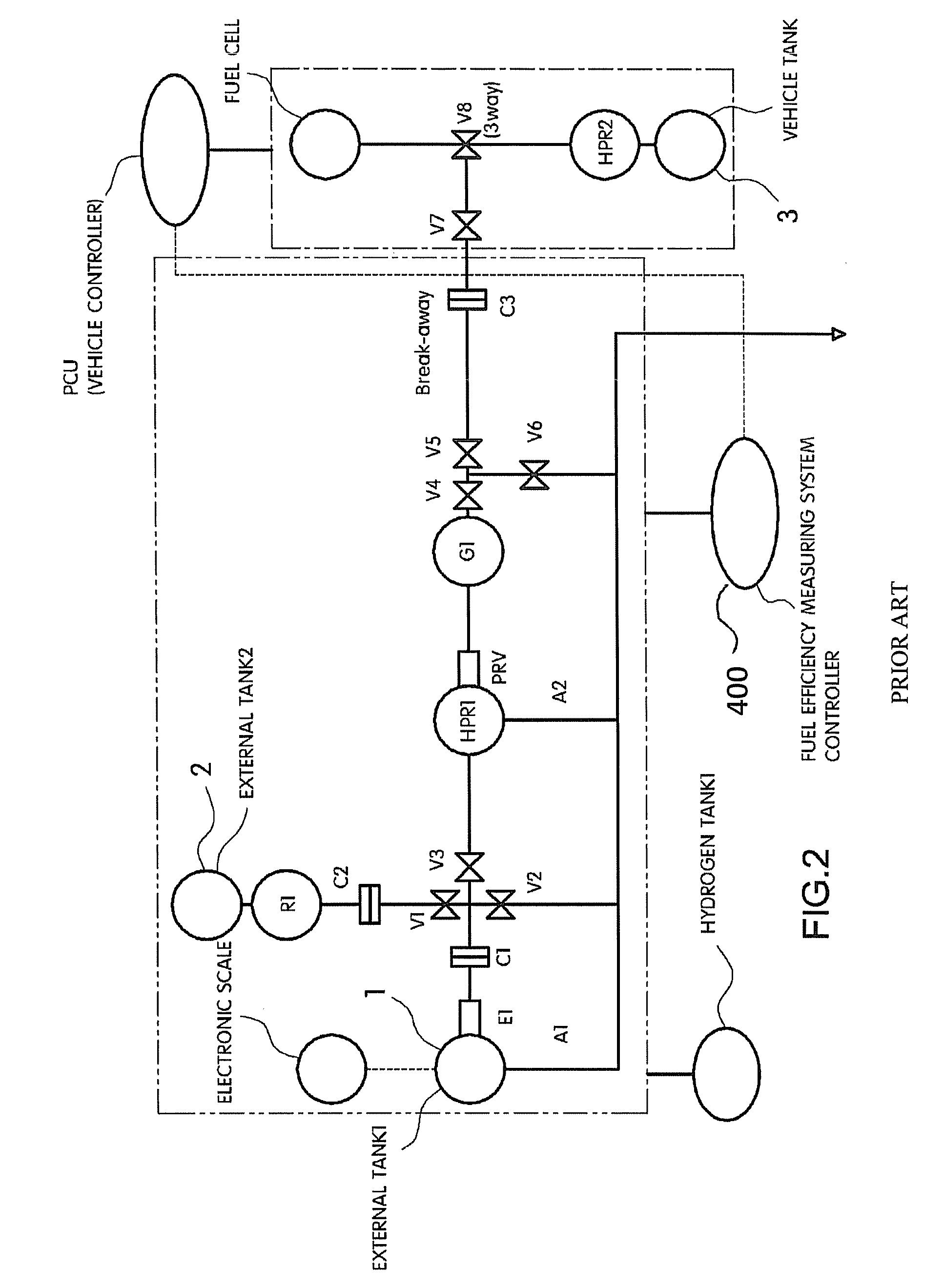
One noted disadvantage is that the previous system is that it is made up of many parts.
As can be seen from FIG. 2, the previous system is made up of numerous parts thereby making the assembly complex.
Accordingly, the assembling processes may be difficult and time consuming.
Thus, it is difficult to manufacture the system and considerably expensive.
Thus, it is difficult to separate the quick coupler from the system when needed.

Method used


Image

  • Fuel efficiency measuring system for fuel cell vehicle
  • Fuel efficiency measuring system for fuel cell vehicle
  • Fuel efficiency measuring system for fuel cell vehicle

Examples


Embodiment Construction

[0024]In one aspect of the present invention a method for measuring the efficiency of a fuel cell vehicle is provided. Initially, a monitoring device, measures the weight of a hydrogen tank prior to traveling of the fuel cell vehicle. Then any residual air within a first hydrogen supply line is removed by a discharging unit prior to the traveling of the vehicle by using hydrogen discharged from a vehicle side hydrogen tank. The fuel cell vehicle is then operated on a dynamo system for a predetermined time. During operation, the hydrogen consumed is supplied via the first hydrogen supply line which is directly connected the fuel cell vehicle. Once the vehicle has traveled for a predetermined time, a monitoring device measures the change in weight of the hydrogen tank after the fuel cell vehicle has operated for the predetermined time period. Additionally, the distance the fuel cell vehicle traveled during the predetermined time period is also measured. The fuel efficiency of the fuel...


PUM


Abstract

The present invention provides an improved fuel efficiency measuring system for a fuel cell vehicle which simplifies various valves and hydrogen lines and modulizes its individual elements. More specifically, the present invention provides an improved fuel efficiency measuring system for a fuel cell vehicle that eliminates a purging hydrogen tank previously used for removing residual air in a hydrogen supply line and instead removes residual air in a hydrogen supply line by using a vehicle side hydrogen tank. Additionally, the present invention simplifies couplers installed in a hydrogen supply line, and considerably reduces manufacturing costs by eliminating a high-cost break-away coupler adapted to couple a fuel efficiency measuring unit and the vehicle side.

Description

CROSS-REFERENCE TO RELATED APPLICATION[0001]This application claims under 35 U.S.C. §119(a) the benefit of Korean Patent Application No. 10-2010-0118498 filed Nov. 26, 2010, the entire contents of which are incorporated herein by reference.BACKGROUND[0002](a) Technical Field[0003]The present invention relates to a fuel efficiency measuring system for a fuel cell vehicle. More particularly, it relates to an improved fuel efficiency measuring system for a fuel cell vehicle which simplifies both various valves and hydrogen lines within the system and modulizes its individual elements.[0004](b) Background Art[0005]A fuel cell is an electricity generation system that does not convert chemical energy of fuel into heat by combustion, but rather electrochemically converts the chemical energy directly into electrical energy in a fuel cell stack. The fuel cell can be applied to the electric power supply of small-sized electrical and electronic devices, for example portable devices, as well as...

Claims


Application Information

Patent Timeline
Patent Type & Authority Patents(United States)
IPC IPC(8): G01M15/00
CPCB60L3/0053B60L3/0069B60L11/1898Y02T90/34B60L2250/10B60L50/72B60L58/30Y02T90/40G01M17/007B60L50/50
Inventor YE, CHANG HWANPARK, JEONG KYUKIM, HYUN JUN
Owner HYUNDAI MOTOR CO LTD
Learn More