
Projector

a projector and light source technology, applied in the field of projectors, can solve the problems of disadvantageous increase of power consumption of the projector, disadvantageous increase of the intensity of the light from the light source, and disadvantageous increase of the electrode wear of the discharge lamp, so as to reduce the amount of wear of the electrodes of the discharge lamp and reduce the brightness of the discharge lamp

Active Publication Date: 2013-08-13
SEIKO EPSON CORP
View PDF3 Cites 7 Cited by
  • Summary
  • Abstract
  • Description
  • Claims
  • Application Information

AI Technical Summary

Benefits of technology

[0008]An advantage of some aspects of the invention is to provide a projector capable of making projected stereoscopic video images appear bright while reducing the amount of wear of electrodes of a discharge lamp.

Problems solved by technology

JP-A-2009-237302, however, describes that simply changing the intensity of the light from a light source disadvantageously accelerates wear of the electrodes of a discharge lamp.
As a result, when stereoscopic video images are projected by using a method for alternately outputting right-eye video images and left-eye video images, the video images disadvantageously appear darker than a case where planar video images are projected in related art.
In this case, however, power consumption of the projector disadvantageously increases, and the increase in drive electric power accelerates degradation of peripheral parts and causes other problems.

Method used


Image

  • Projector
  • Projector
  • Projector

Examples


experimental example

2. Experimental Example

[0143]A description will next be made of an experimental example using the projector 500 according to Variation 1 of the present embodiment.

[0144]In the present experiment using a discharge lamp driven at a drive voltage of 70 V in an initial state, the experiment was so conducted that the electrodes of the discharge lamp wore to a point where the drive voltage for driving the discharge lamp increased to 110 V. Further, in the present experiment, the shapes of the electrodes of the discharge lamp were estimated and evaluated based on variation in the drive voltage for driving the discharge lamp and the brightness thereof obtained when the first and second control processes were carried out at certain drive electric power. Table 1 shows evaluation results obtained in the present experiment.

[0145]

TABLE 1Shapes of protrusionsDrive electricFirst controlSecond controlpowerprocessprocess200 Wbadfair210 Wfairgood220 Wfairgood230 Wgoodgood

[0146]In Table 1, “good” indi...


PUM


Abstract

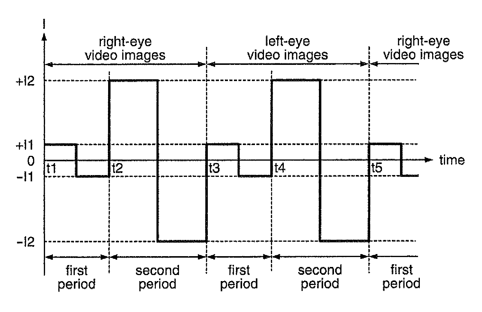
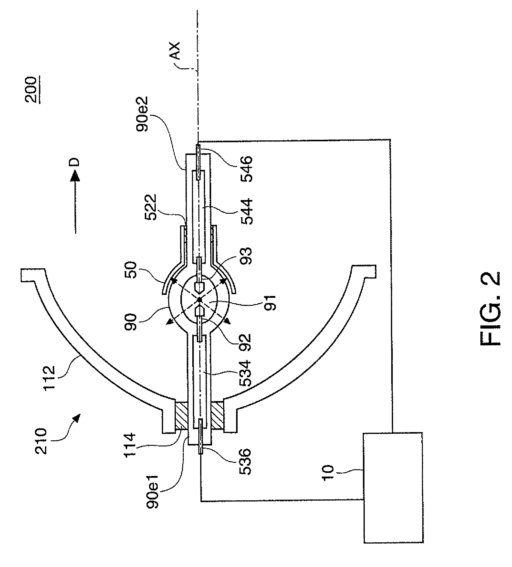
A projector includes a discharge lamp, a discharge lamp driver that supplies the discharge lamp with a current, a voltage detector that detects a drive voltage for driving the discharge lamp, and a controller that controls the discharge lamp driver. The controller carries out a first control process in which the discharge lamp driver is so controlled that an absolute magnitude of the drive current in a first period is smaller than that in a second period and that an AC current is supplied to the discharge lamp in a second period. The first control process includes a first electric power control process in which first average drive electric power is determined based on the voltage detected by the voltage detector and a current is supplied to the discharge lamp in such a way that average drive electric power is set at the first average drive electric power.

Description

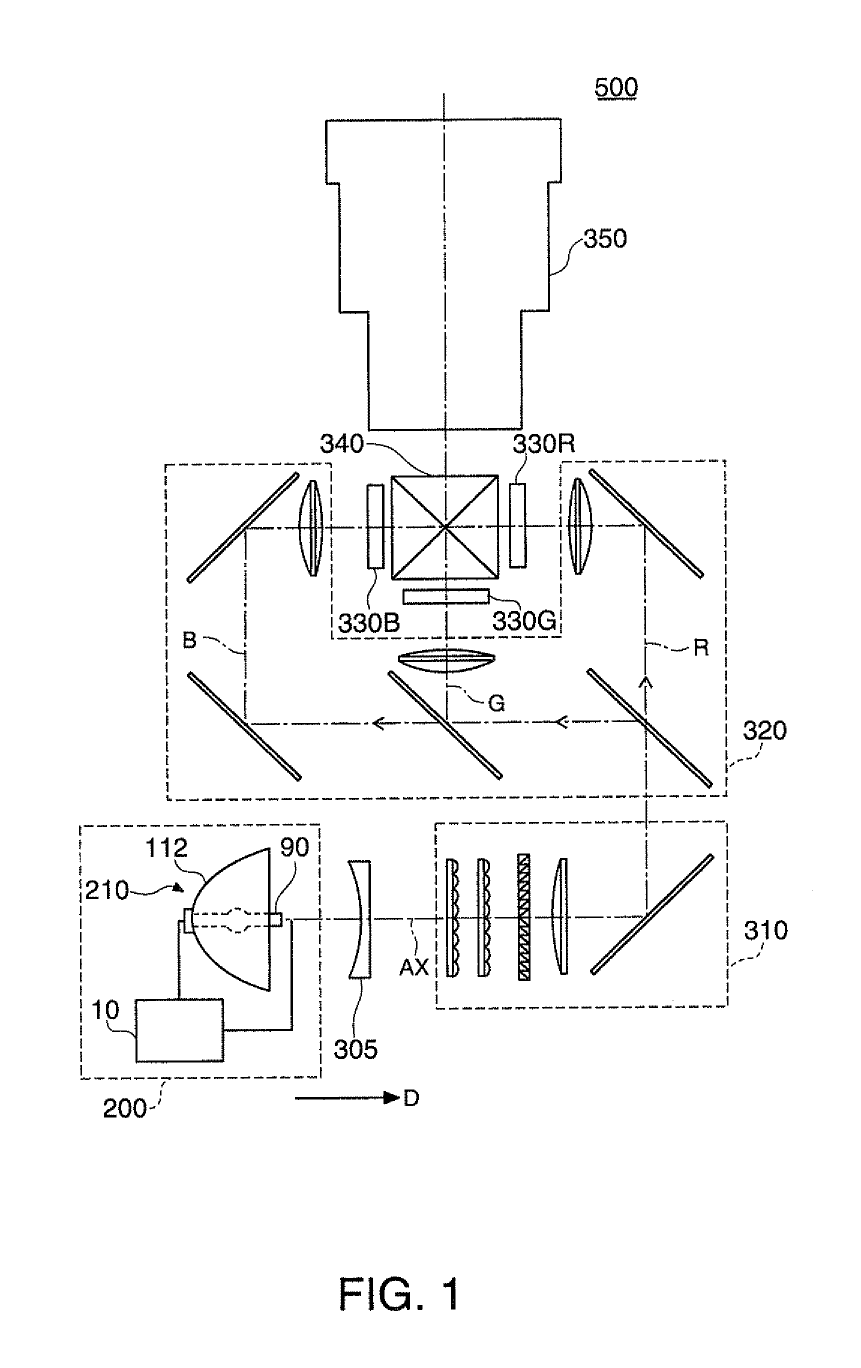
BACKGROUND[0001]1. Technical Field[0002]The present invention relates to a projector.[0003]2. Related Art[0004]Projectors using a high-pressure mercury lamp, a metal halide lamp, or any other suitable discharge lamp have been in practical use. For example, JP-A-2003-102030 discloses a projector having a mechanism for changing the intensity of the light from a light source in accordance with the color selected by a color separation system or any other suitable mechanism and in synchronization with a video signal. JP-A-2009-237302, however, describes that simply changing the intensity of the light from a light source disadvantageously accelerates wear of the electrodes of a discharge lamp.[0005]Further, projectors using a high-pressure mercury lamp, a metal halide lamp, or any other suitable discharge lamp to output stereoscopic video images have recently been brought into practical use.[0006]To output stereoscopic video images, for example, video images for the right and left eyes ar...

Claims


Application Information

Patent Timeline
Patent Type & Authority Patents(United States)
IPC IPC(8): G03B21/20H04N13/363
CPCG03B21/2026G03B21/2053G03B35/16H04N5/74H05B41/2888H04N13/0438H04N13/0459H05B41/14H04N9/3155H04N13/341H04N13/363
Inventor SATO, SHUNTERASHIMA, TETSUO
Owner SEIKO EPSON CORP
Learn More