Cutter mechanism and printer with a cutter

a cutter and cutter technology, applied in the direction of printing, typewriters, metal working devices, etc., can solve the problems of difficult to expect a high swinging property in the blade width direction, distorted cut end surface, and left uncut portions, etc., and achieve improved reliability, enhanced recording sheet quality, and high usability.

Active Publication Date: 2013-08-13
SEIKO INSTR INC
View PDF6 Cites 5 Cited by
  • Summary
  • Abstract
  • Description
  • Claims
  • Application Information

AI Technical Summary

Benefits of technology

[0017]The present invention has been made in view of the above-mentioned circumstances, and an object of the present invention is therefore to provide a cutter mechanism capable of achieving a high swinging property of the fixed blade, reliably cutting the recording sheet from both right and left sides thereof without leaving an uncut portion, etc., and achieving simplification of a shape of the fixed blade and cost reduction.

Problems solved by technology

If a difference is seen between press-contact forces, there is a fear that an uncut portion, etc. are left, or a fear that a cut end surface is distorted.
However, because the two or more support portions inserted in the receiving holes are formed on the fixed blade, it has been difficult to expect a high swinging property in the blade width direction.
However, because the two or more support portions are formed, it is difficult to make the most of each of the plays, and a swinging amount is necessarily restricted.
Therefore, the high swinging property in the blade width direction cannot be expected, and it has been sometimes difficult to equalize the press-contact forces at the right and left two contact points during cutting from beginning to end.
Consequently, there remains a fear that an uncut portion, etc are still left when the recording sheet is cut.
Further, though the fixed blade is typically manufactured by punching with use of a die, a die shape is complex because two or more support portions are formed.
In particular, as a material for the fixed blade, a metal material with high hardness is often adopted, and hence a high load tends to act on the die during punching.
Therefore, as the die shape becomes more complex and fine, chips and cracks are more likely to occur, and the life of the die is more likely to decrease.
As a result, a manufacturing cost of the fixed blade is influenced, which leads to an increase in the cost of the fixed blade.

Method used


Image

  • Cutter mechanism and printer with a cutter
  • Cutter mechanism and printer with a cutter
  • Cutter mechanism and printer with a cutter

Examples


Embodiment Construction

[0068]Hereinafter, embodiments according to the present invention are described with reference to FIGS. 1 to 26.

[0069]Note that, in this embodiment, a thermal printer is exemplified as one example of a printer with a cutter.

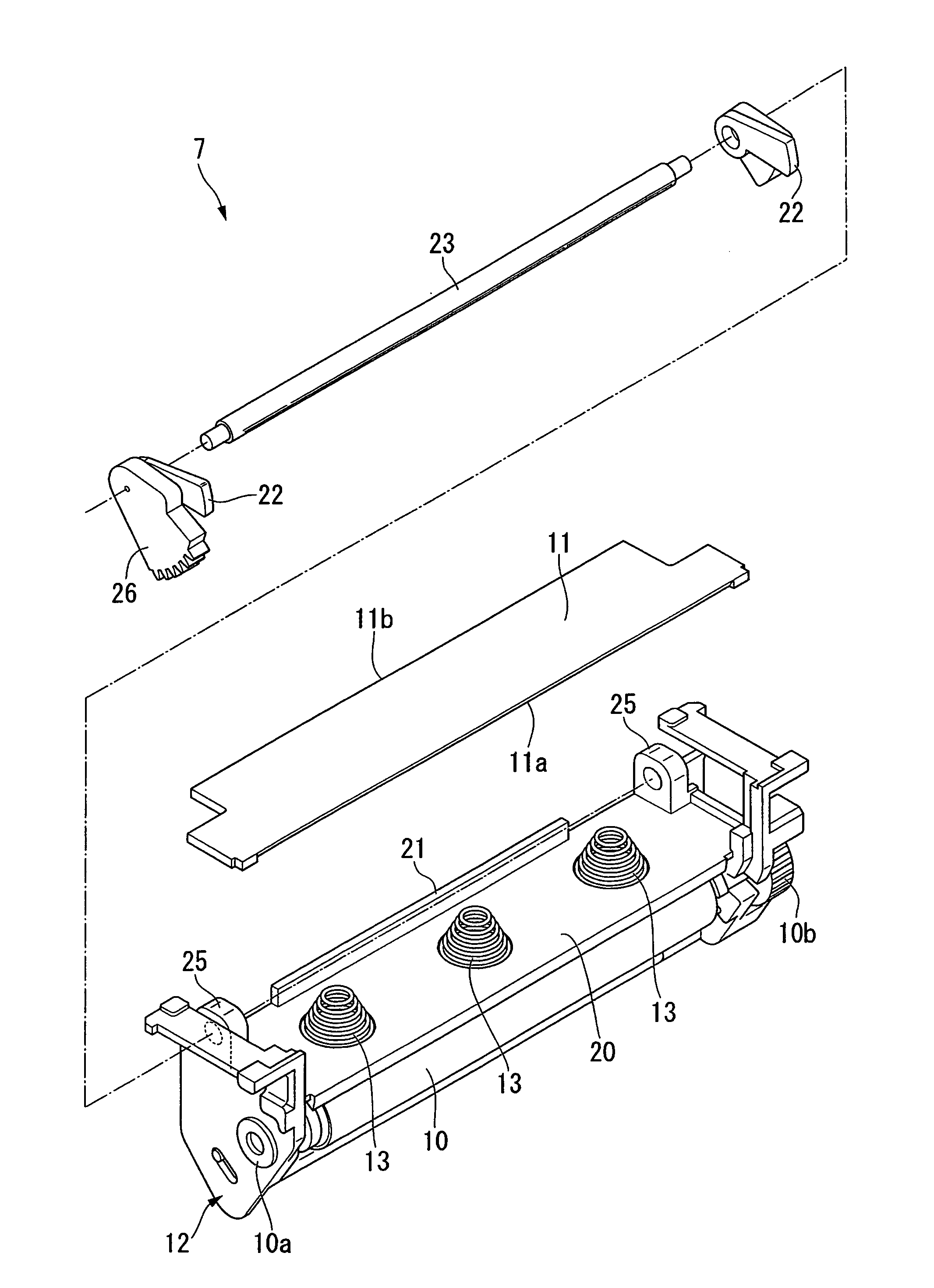
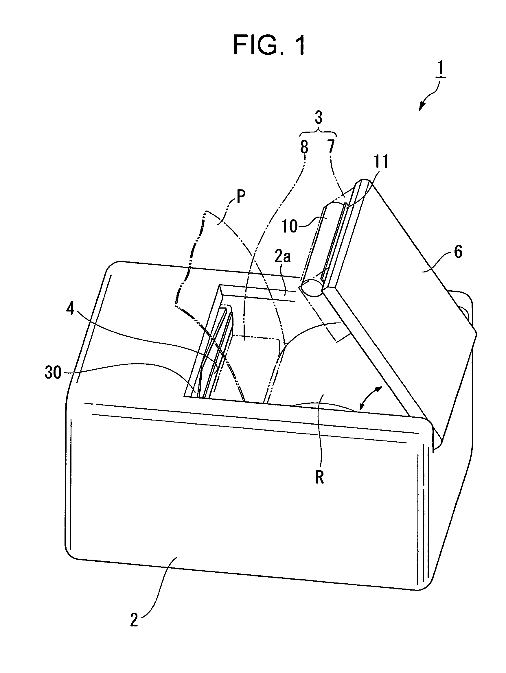
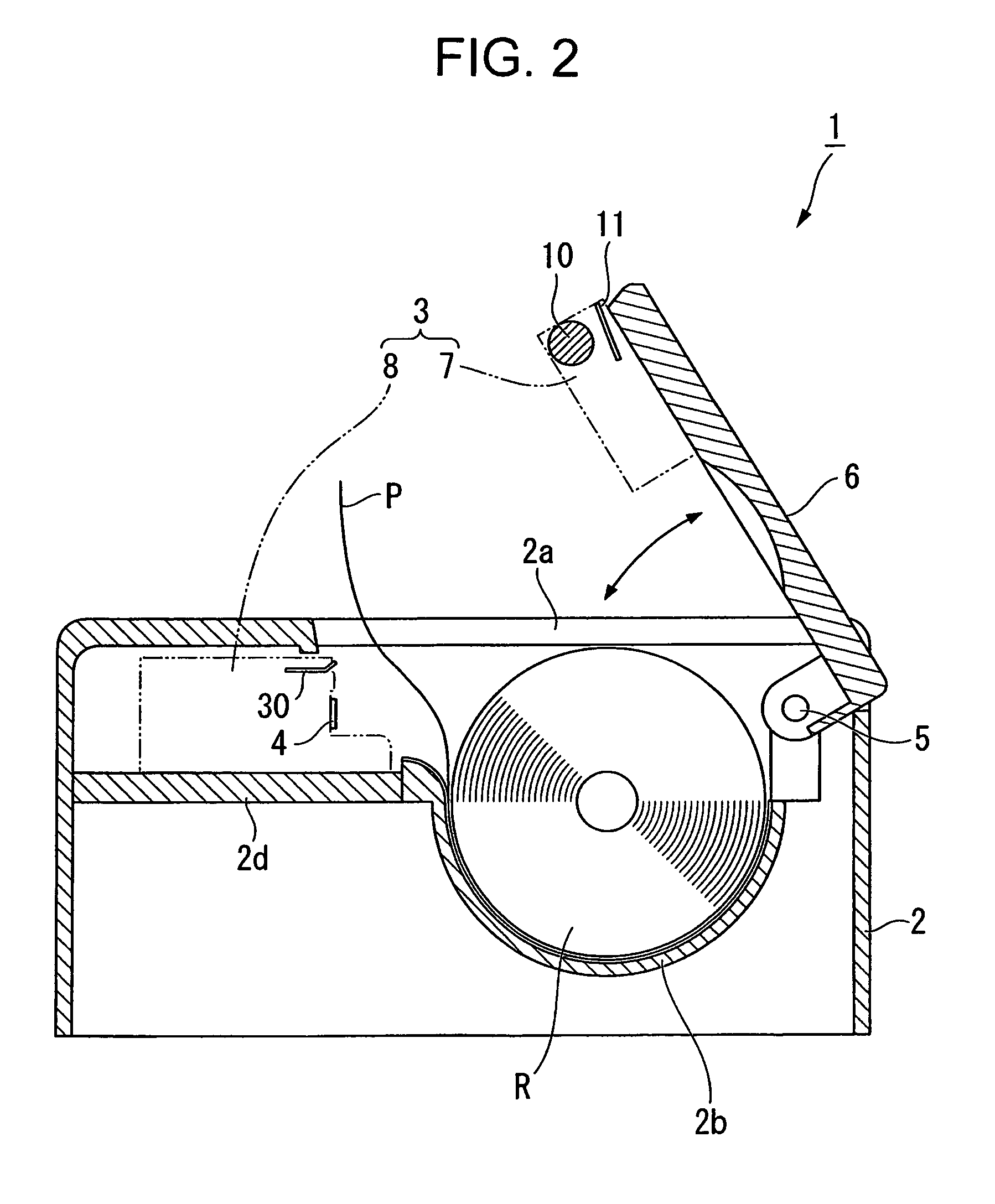
[0070]A thermal printer 1 of this embodiment is a printer that can appropriately cut a recording sheet P after printing on the recording sheet P pulled out from a paper roll R to use as a ticket, a receipt, and the like, and mainly includes a casing 2, a cutter mechanism 3, and a thermal head (printing unit) 4, as illustrated in FIG. 1 and FIG. 2.

[0071]The casing 2 is a casing molded from a plastic or a metal material, and is formed into a box-shape with an insertion port 2a opened at the upper surface. A mounting board 2b for mounting the paper roll R inserted from the insertion port 2a is arranged in the interior of the casing 2. The mounting board 2b is formed to curve into an arcuate shape, and enables the cylindrical paper roll R to be stably mounted.

[0072]A...


PUM

PropertyMeasurementUnit
widthaaaaaaaaaa
contacting pressureaaaaaaaaaa
press-contact forcesaaaaaaaaaa

Abstract

A cutter mechanism has a fixed blade and slidable blade which cooperates with the fixed blade to cut a recording sheet. The fixed blade is biased in a direction away from a base portion by a biasing member. A holder supports the fixed blade away from the base portion to cause a cutting edge of the fixed blade to swing up and down and permit opposite ends of the fixed blade to be pushed down at least in the direction of the base portion. The fixed blade holder has a wall portion positioning the fixed blade in a sliding direction of the slidable blade, a first regulating member that regulates lifting of the fixed blade cutting edge, and a second regulating member that regulates lifting of the fixed blade root portion in a state in which a gap is formed between the base portion and the root portion.

Description

BACKGROUND OF THE INVENTION[0001]1. Field of the Invention[0002]The present invention relates to a cutter mechanism that cuts a recording sheet while sandwiching the recording sheet by causing a movable blade to slide with respect to a fixed blade, and to a printer with a cutter including the cutter mechanism.[0003]2. Description of the Related Art[0004]Nowadays, a great number of various types of thermal printers, which performs printing by pressing a thermal head against a special recording sheet that changes color when heat is applied thereto, are provided. In particular, use is suitably made in printing of receipts, tickets, and the like because smooth character printing and colorful graphic printing are possible without using toner, ink, and the like.[0005]As represented by the thermal printers, numerous printers with a cutter provided with a cutter mechanism for cutting the printed recording sheet are known. The printer with a cutter is used by being incorporated in, for examp...

Claims


Application Information

Patent Timeline
Patent Type & Authority Patents(United States)
IPC IPC(8): B41J11/70B41J11/66B26D1/08
CPCB26D1/085B26D7/2614B41J2/32B41J29/02B41J29/13B41J29/38B26D7/00B26D7/2628B26D2007/2685B41J11/70Y10T83/4645Y10T83/8749
Inventor KOHIRA, HIROYUKI
Owner SEIKO INSTR INC
Why Eureka
Try Eureka