Device for receiving a test sample

a technology for receiving devices and test samples, which is applied in the direction of material testing goods, lighting and heating apparatus, electric heating for furnaces, etc., can solve the problems of inability to achieve the potentially high lateral and vertical resolution of scanning probe microscopes in commercial appliances, and complicated structure of such devices for receiving test samples

Active Publication Date: 2013-08-13
BRUKER NANO INC +1
View PDF15 Cites 25 Cited by
  • Summary
  • Abstract
  • Description
  • Claims
  • Application Information

AI Technical Summary

Problems solved by technology

However, the structure of such a device for receiving the test sample is complicated, because, for example, several components must be arranged and screwed together in a suitable way.
Access by a scanning probe microscope from above is possible, but there are restrictions which are unacceptable.
For example, it is not possible to achieve the potentially high lateral and vertical resolution of the scanning probe microscope in a commercial appliance, particularly where testing takes place in a liquid medium such as water or buffer, for example.
A further major problem is thermal drift, whereby particularly drift perpendicular to the test sample may entail that the relatively small scanning range of a scanning probe microscope, of, for example, 15 μm, is exceeded and that the probe used for testing either loses contact with the test sample or even collides with it.
Thermal drift in the sample plane is also problematic, as it is then particularly difficult to relocate a point on the sample if the test sample undergoes pronounced change due to a temperature fluctuation.

Method used


Image

  • Device for receiving a test sample
  • Device for receiving a test sample
  • Device for receiving a test sample

Examples


Embodiment Construction

[0019]The invention is described in more detail below using sample embodiments with reference to figures of a drawing.

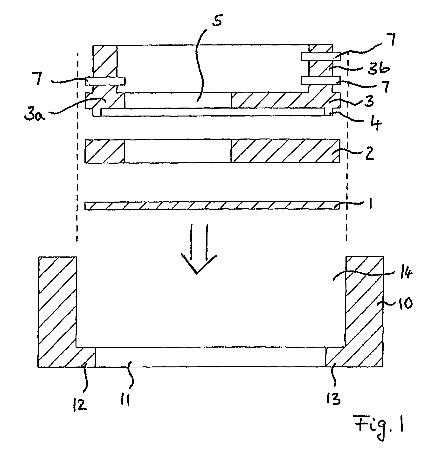
[0020]FIG. 1 is a cross-section of a device for receiving a test sample;

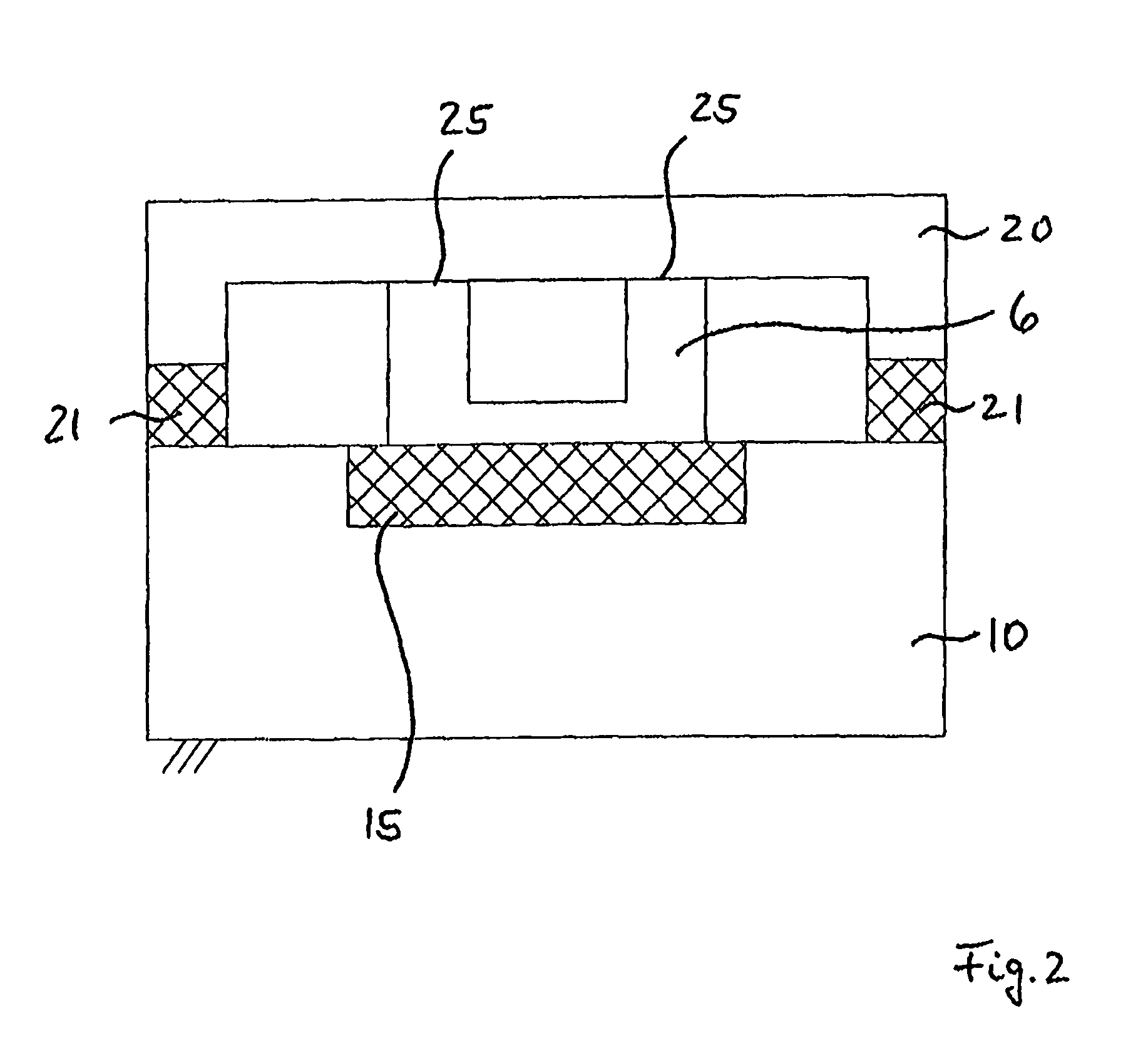
[0021]FIG. 2 is a schematic diagram to explain the minimisation of drift achieved;

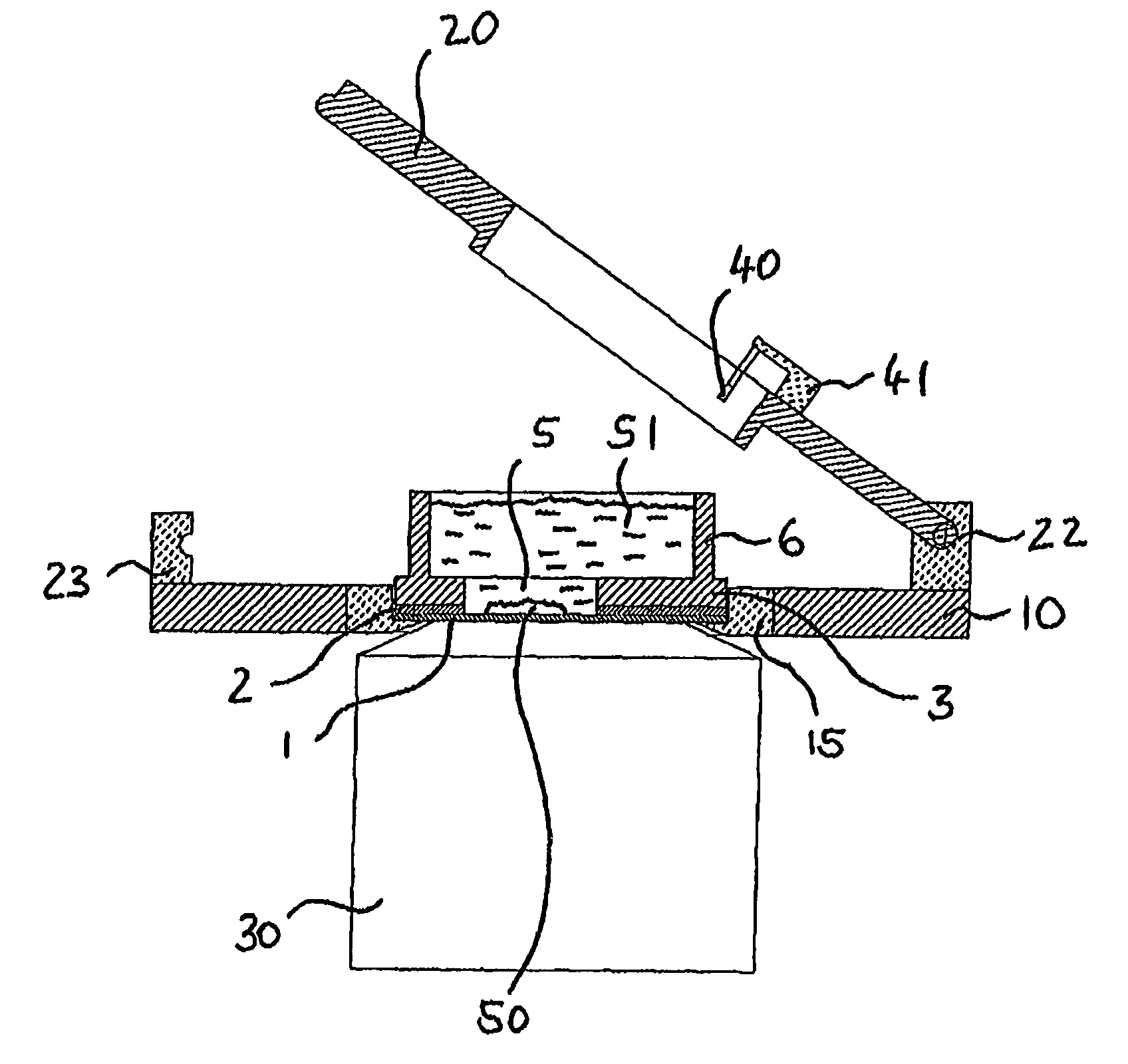
[0022]FIG. 3 is a cross-section of a further device for receiving a test sample, with a tilting mechanism, and

[0023]FIG. 4 is a device for receiving a test sample in accordance with FIG. 3, with the tilting mechanism tilted down.

[0024]FIG. 1 shows components of a device for receiving a test sample in cross section. The device is integrated into test apparatus for examination of the test sample and makes it possible to examine the test sample by means of different test procedures. In accordance with FIG. 1, a preparation component in the form of cover slip 1 is arranged on a support 10. The support 10 has a support opening 11, which is demarcated by support sections 12, 13.

[0025]The cover slip 1 is preferably a comme...


PUM

PropertyMeasurementUnit
diametersaaaaaaaaaa
transparentaaaaaaaaaa
surface areaaaaaaaaaaa

Abstract

The invention relates to a device for receiving a test sample, particularly sample holders for combined examination of the test sample by a test procedure combined with another test procedure, which differs from the first test procedure, with a planar preparation component (1) in a transparent material with a preparation surface on which the test sample can be prepared, wherein a test path for the introduction of a test facility for carrying out the test procedure is formed on one side of the preparation component (1) and another test path for the introduction of a test facility for carrying out the other test procedure on the test sample is formed on an opposite side of the preparation component (1), wherein a supporting and covering element (3a) which has an aperture (5) through which the test path is formed is pressed against the preparation component (1) on one side (FIG. 1).

Description

CROSS REFERENCE TO RELATED APPLICATIONS[0001]This application is a national stage application under 35 USC 371 of International Application No. PCT / DE2005 / 0013195 filed on Aug. 4, 2005, which claims priority to German Patent Application No. 202004012394.0 filed on Aug. 5, 2004. The disclosure of International Application No. PCT / DE2005 / 0013195 and German Patent Application No. 202004012394.0 are hereby incorporated by reference.[0002]The invention concerns a device for receiving a test sample, particularly sample holders, for combined examination of the test sample by a test procedure combined with another test procedure which differs from the first test procedure.STATE OF THE ART[0003]Scanning probe microscopy (SPM) is a method of measuring surface properties, for example topology. Volumetric properties close to the surface can also be determined, e.g. the elasticity of a test sample. The scanning probe microscopy is frequently disadvantaged by the fact that chemical properties of ...

Claims


Application Information

Patent Timeline
Patent Type & Authority Patents(United States)
IPC IPC(8): G01N21/03G01N21/35G01Q30/14
CPCB82Y35/00G01Q30/14G01N21/0303G01N21/03G01N21/0332
Inventor SUNWOLDT, OLAFKNEBEL, DETLEF
Owner BRUKER NANO INC
Why Eureka
Try Eureka