Micro channel plate

a microchannel plate and microchannel technology, applied in the field of microchannel plates, can solve the problems of difficult manufacturing of thin mcps with minute channels, and achieve the effects of reducing distortion, preventing channel breakage failure of external electrodes for supplying voltage, and facilitating handling

Active Publication Date: 2013-08-13
HAMAMATSU PHOTONICS KK
View PDF11 Cites 1 Cited by
  • Summary
  • Abstract
  • Description
  • Claims
  • Application Information

AI Technical Summary

Benefits of technology

[0007]Although influence in the processing by thermal and stress loads on the porous part 10 and the poreless part 11 of the MCP differ, in the round-shaped MCP main body 300, deformation is suppressed in any direction because of the poreless part 11 surrounding the circumference. On the other hand, since the degree of deformation differs in each direction in the case of the rectangular MCP main body 400, distortion as shown in FIG. 12 (b) or warping as shown in FIGS. 12 (c) and (d) easily occurs and therefore it was difficult to manufacture a thin MCP having a minute channel.
[0008]Therefore, an object of the present invention is to provide a rectangular and thin MCP which has a minute channel and which can suppress deformation.
[0011]The MCP of the present invention has a solid glass part on three or less side and is formed to allow a porous part to extend to the other side part. Thus, in a case where thermal or stress load is applied, the load is absorbed by channel deformation in the porous part so that deformation in the porous surface direction such as warping can be suppressed. Moreover, the electrode is provided so as to cover the solid glass part and a portion where the electrode covers the solid glass part becomes a voltage supply part. Thus, breakage failure of a channel by an external electrode for supplying voltage can be prevented and it becomes possible to supply voltage without causing breakage failure of a channel.
[0012]Providing the solid glass on two sides, especially on two opposed sides ensures strength and simultaneously allows easier handling thereof. Providing the solid glass on a shorter side effectively reduces distortion caused by generation of stress. If the bias direction and extending direction of a side wall are matched with each other, each channel can be efficiently utilized. Setting the output side electrode smaller stabilizes operation.

Problems solved by technology

On the other hand, since the degree of deformation differs in each direction in the case of the rectangular MCP main body 400, distortion as shown in FIG. 12 (b) or warping as shown in FIGS. 12 (c) and (d) easily occurs and therefore it was difficult to manufacture a thin MCP having a minute channel.

Method used


Image

  • Micro channel plate
  • Micro channel plate
  • Micro channel plate

Examples


first embodiment

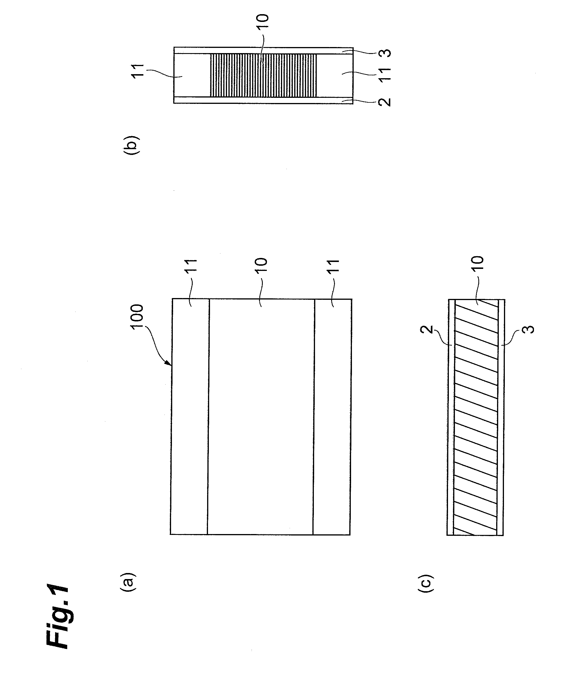
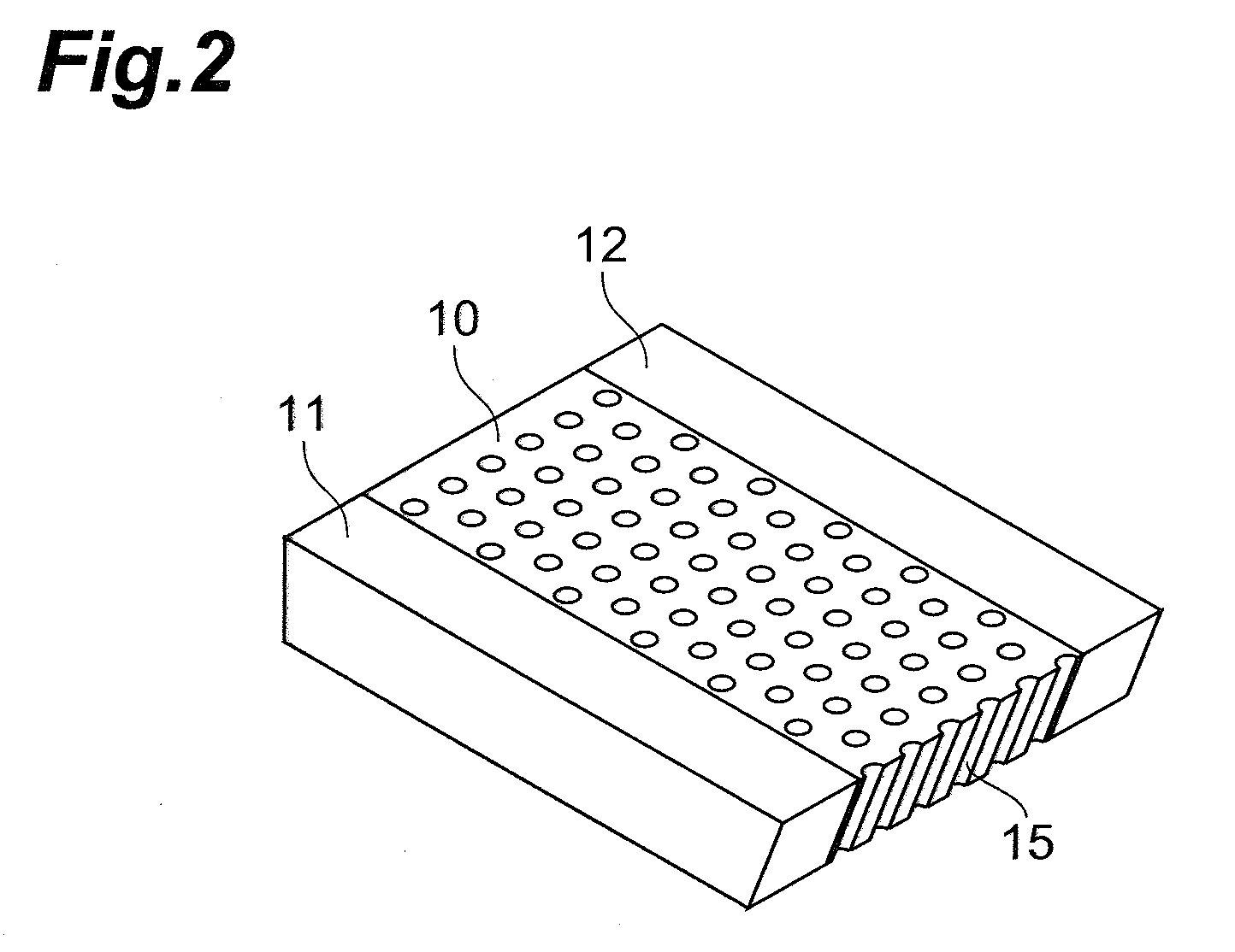
[0021]FIG. 1 (a) to FIG. 1 (c) indicate a rectangular MCP of the present invention. FIG. 1 (a) is a front elevational view, FIG. 1 (b) and FIG. 1 (c) are a longitudinal-sectional view and a cross-sectional view. FIG. 2 is a perspective view of the main body part (imaginary view). The MCP 100 has a rectangular plate shape and has a plurality of pores (channels) 15 penetrating in the thickness direction of the MCP 100. Hereinafter, an area where the channel 15 is provided will be called a porous part 10. The channels 15 are parallel to each other and an axial direction thereof is inclined by a predetermined degree in a longitudinal direction of the MCP 100 toward a perpendicular vector of a surface of the MCP 100 (this angle is called a bias direction). Directions of hatching indicating the porous part 10 in FIGS. 1 (b) and (c) indicate axial directions of each of the channels 15 in a simulated manner. Poreless parts 11 are formed extending in the longitudinal direction of the MCP 100...

fifth embodiment

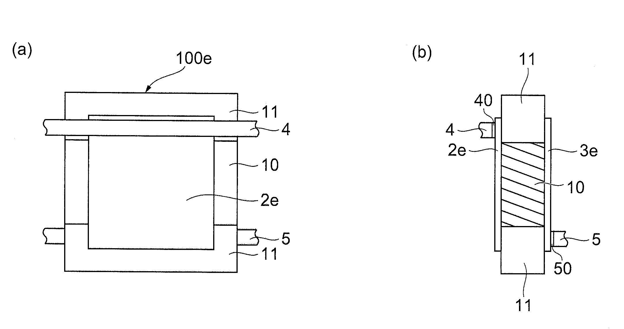
[0028]FIG. 7 (a) and FIG. 7(b) are views showing a rectangular MCP of the present invention. In this embodiment, a difference is that stick-shaped electrodes 4 and 5 are attached to surfaces of portions on the poreless part 11 by conductive adhesive agents 40 and 50. According to this embodiment, application of voltage to the MCP 100e can be reliably conducted on the poreless part 11.

[0029]In the fifth embodiment, an example where a stick-shaped electrode is used as the electrode was explained. However, a configuration in which film-shaped or thin plate-shaped electrodes are attached on the surfaces of the MCP main body or a configuration in which other equipment is used to cause the electrodes to sandwich the MCP 100 may be adopted. In either case, it is preferable that the electrodes cover the poreless part 11 on the both sides.

[0030]The rectangular MCP of the present invention is not limited to the embodiments by which solid glass parts are provided on two sides opposed to each o...


PUM


Abstract

An MCP has a rectangular plate shape and has a porous part, to which a plurality of pores (channels) penetrating in the thickness direction are disposed, and a poreless part including a solid glass or the like to which the channels are not provided on the both sides of the porous part. Then, on both surfaces of the MCP, an input side electrode and an output side electrode are respectively formed so as to cover the poreless parts on the both surfaces while sandwiching the porous part.

Description

BACKGROUND OF THE INVENTION[0001]1. Field of the Invention[0002]The present invention relates to a micro channel plate for intensifying and outputting an electron, an ion, or the like and especially relates to a micro channel plate having a rectangular shape.[0003]2. Related Background Art[0004]There has been known a detection unit using a micro channel plate (MCP) for intensifying and outputting an incident electron or an ion so that a small amount of an electron, an ion, or the like can be accurately detected. There are two types of such an MCP: a round one and a rectangular one. WO 2006 / 030820 A1 discloses an example of a manufacturing method of such an MCP.SUMMARY OF THE INVENTION[0005]FIG. 9 shows an example of a rectangular MCP. An MCP 200 comprises a main body having only a porous part 10, which includes a plurality of pores called channels and electrodes 2 and 3 which are respectively disposed on both surfaces of a main body. FIG. 10 shows an example of a manufacturing metho...

Claims


Application Information

Patent Timeline
Patent Type & Authority Patents(United States)
IPC IPC(8): H01J43/04H01J43/06
CPCH01J43/246
Inventor SUZUKI, AKIOIIZUKA, ETSUOUCHIYAMA, TOSHIYUKISUYAMA, MOTOHIRO
Owner HAMAMATSU PHOTONICS KK
Why Eureka
Try Eureka