Multiple-channel transmission over a single-wire bus

a single-wire bus and multi-channel technology, applied in the field of data transmission, can solve the problem that the master circuit can only transmit a single signal to the slave circuit, and achieve the effect of increasing the transmission rate of a single-wire protocol

Active Publication Date: 2013-08-13
STMICROELECTRONICS (ROUSSET) SAS
View PDF6 Cites 253 Cited by
  • Summary
  • Abstract
  • Description
  • Claims
  • Application Information

AI Technical Summary

Problems solved by technology

Further, the master circuit can only transmit a single signal to slave circuits.

Method used


Image

  • Multiple-channel transmission over a single-wire bus
  • Multiple-channel transmission over a single-wire bus
  • Multiple-channel transmission over a single-wire bus

Examples


Embodiment Construction

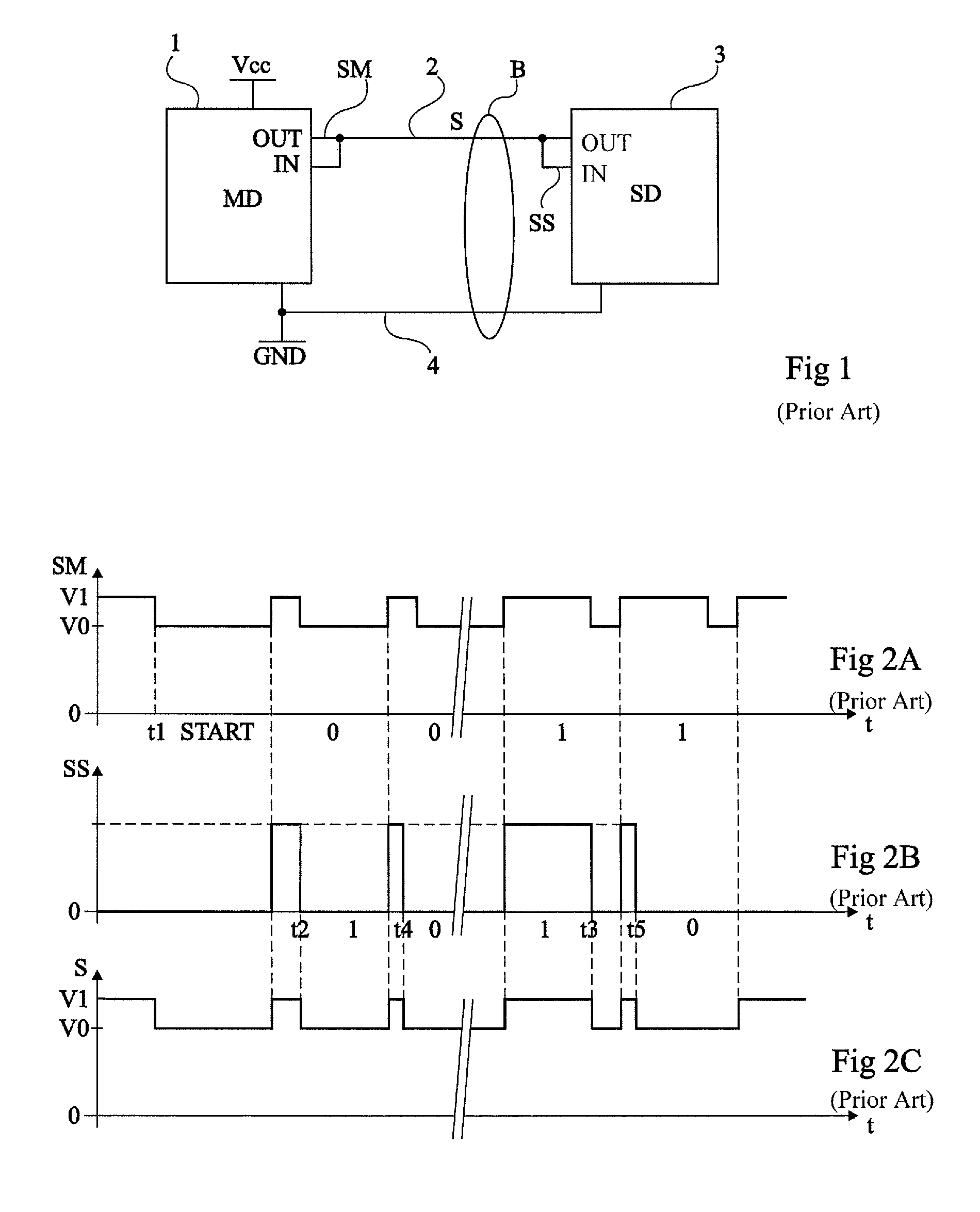
[0040]The same elements have been designated with the same reference numerals and the timing diagrams have been drawn out of scale.

[0041]For clarity, only those steps and elements which are useful to the understanding of the present invention have been shown and will be described. In particular, the generation of the signals on the master device or slave device side has not been detailed, the present invention being compatible with the usual generation of signals in a master-slave protocol exploiting a single-wire connection.

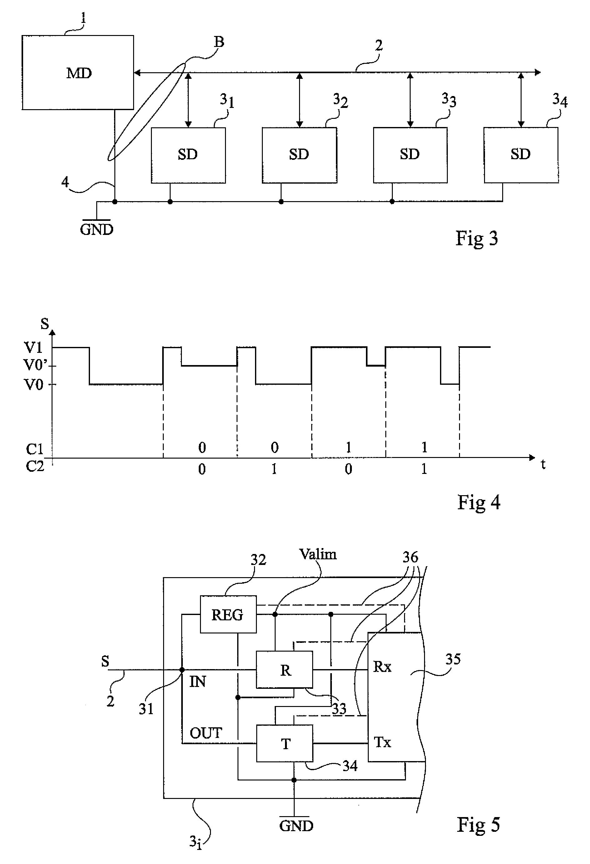
[0042]FIG. 3 is a block diagram of an embodiment of a system of communication between a master device 1 (MD) and one or several slave devices 31, 32, 33, 34 (SD) over a bus B formed of a single-wire connection 2 for transmitting a power supply, clock, and data signal and of a common reference wire 4 (for example, ground GND).

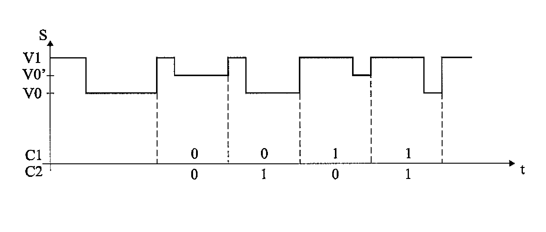
[0043]FIG. 4 is a timing diagram illustrating the level of signal S according to an embodiment of the system of FIG. 3.

[0044]As compared wi...


PUM


Abstract

Apparatus and methods are described that enable concurrent transmission of multiple data signals including clock, synchronization, and power over a single-wire bus between a master device and one or more slave devices. A first transmission channel from the master device to the slave device may modulate the width of periodic pulses between a first voltage level and a second voltage level with respect to a reference potential. A second transmission channel may modulate the amplitude of at least one of the first and second voltage levels to at least one third voltage level. Concurrent communications between a master device and one or more slave devices over a single-wire bus can be achieved.

Description

CROSS REFERENCE TO RELATED APPLICATIONS[0001]This application is a U.S. National Stage patent application based on PCT Application Number PCT / FR2009 / 051418, filed on Jun. 16, 2009, entitled “Multichannel Transmission on Unifilar Bus”, which application claims the priority benefit of French patent application number 08 / 54983, filed on Jul. 22, 2008, entitled “Multichannel Transmission on Unifilar Bus,” which applications are hereby incorporated by reference to the maximum extent allowable by law.BACKGROUND OF THE INVENTION[0002]1. Field of the Invention[0003]The present invention generally relates to data transmissions between two electronic circuits. The present invention more specifically relates to the simultaneous transmission, over the same wire, of a power supply, clock, and data signal between a master circuit and one or several slave circuits.[0004]2. Discussion of the Related Art[0005]Communication protocols between a master circuit and a slave circuit which transmit, over t...

Claims


Application Information

Patent Timeline
Patent Type & Authority Patents(United States)
IPC IPC(8): H04B3/00
CPCG06F13/4295H04B3/548H04B14/023H04L25/4902H04B2203/5416
Inventor TAILLIET, FRANCOIS
Owner STMICROELECTRONICS (ROUSSET) SAS
Why Eureka
Try Eureka