Patient positioning system for panoramic dental radiation imaging system

a radiation imaging and positioning system technology, applied in the field of dental radiation imaging systems, can solve the problems of not providing proper forward-backward positioning (the y axis), and achieve the effect of convenient and convenient mechanisms for assessing proper positioning

Active Publication Date: 2013-08-13
MIDMARK
View PDF25 Cites 8 Cited by
  • Summary
  • Abstract
  • Description
  • Claims
  • Application Information

AI Technical Summary

Benefits of technology

[0006]The present invention relates to panoramic dental radiation imaging, and in particular to a patient positioning system for a panoramic dental radiation imaging system to achieve desired positioning of the patient for rotation of a radiation source and receiver about a patient's skull, in which positioning of the patient along all necessary axes, stabilization of the patient in the proper position, and easy and convenient mechanisms to assess proper positioning are provided.
[0008]A mirror is mounted to the upright support by a mechanism that permits the mirror to be rotated outward from the upright support, in two directions, so as to enable the technician to see the lasers on the patient's face from the technician's position on either side of the positioning arm. The mirror mounting mechanism includes a frame, a top base member, and a bottom base member. The frame has a pair of posts spaced apart at the top, and another pair of posts spaced apart at the bottom. Each base member includes a pair of notches which, when the mirror is in a flat position, each fit around a respective one of the posts. The mounting mechanism also includes a pair of plates, and a pair of brackets coupled to the plates, the brackets having slots which allow the brackets to move the distance of the slot length as the brackets slide along the posts, which allows the plates to move to the angled positions. Hinges are coupled to the plates and base members, and capable of rotating about hinge pins. At least one tab is provided on the lower base member, such that when a user pulls on one of the tabs, the hinge tubes coupled to the plates rotate about the hinge pins, and plates on same side of the hinges as tab move the corresponding bracket, allowing movement of the base members and the mirror coupled thereto to an angle in the direction the tab is pulled.

Problems solved by technology

However, while these types of platforms aid in proper vertical alignment (along the Z axis) of the skull to adjust the height of the radiation source and detector, it does not provide for proper forward-backward positioning (the Y axis), positioning in right-left direction (the X axis), stabilizing the patient in the apparatus, or providing a convenient way for a technician to assess proper positioning.

Method used


Image

  • Patient positioning system for panoramic dental radiation imaging system
  • Patient positioning system for panoramic dental radiation imaging system
  • Patient positioning system for panoramic dental radiation imaging system

Examples


Embodiment Construction

[0025]This application is being filed at the same time as a patent application on a motion system for a panoramic dental radiation imaging system, and a patent application on a removable radiation sensor for a dental imaging system, and a design patent application on a dental imaging system, all filed on the same day as this application and assigned to the same assignee. The disclosure of each of those other patent applications is incorporated herein by reference.

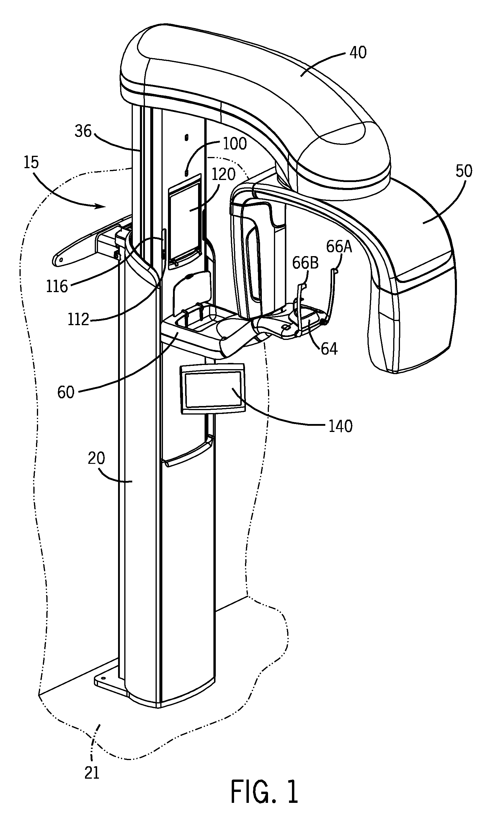
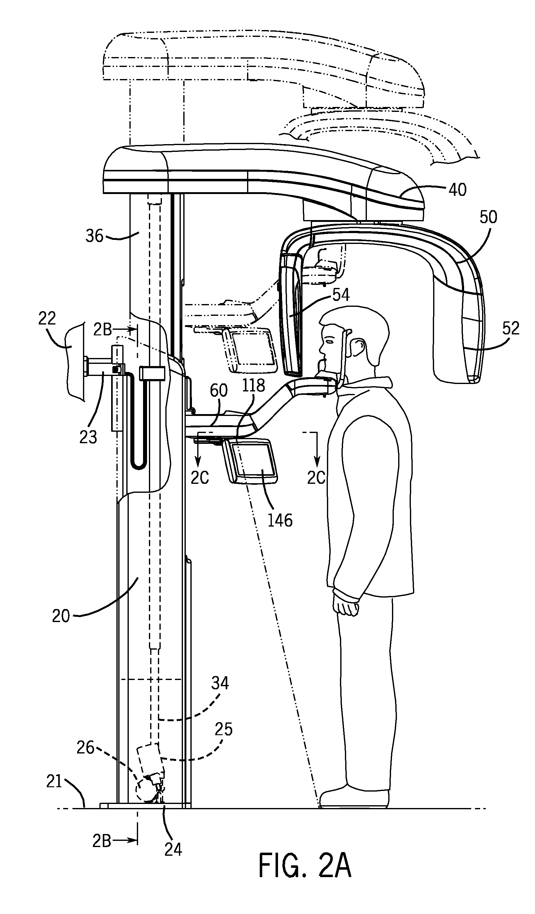
[0026]One embodiment of a panoramic dental radiation imaging system 10 and patient positioning system therefor is shown in the figures. While the invention may be susceptible to embodiment in different forms, there is shown in the drawings, and herein will be described in detail, certain illustrative embodiments with the understanding that the present disclosure is to be considered an exemplification of the principles of the invention, and is not intended to limit the invention to those as illustrated and described herein. ...


PUM


Abstract

A patient positioning system for a panoramic dental radiation imaging system, including an upright support, and a patient positioning arm with chin rest mounted thereto. Wands are each rotatably connected to the patient positioning arm and connected together so as to move at identical angles of rotation, but in the opposite direction. Lasers, including a mid-sagittal, a Frankfort Plane, two cuspid, and one toe laser, each providing a line of visible laser light directed at a respective area of a patient's face, or at the floor, assist a technician in properly positioning the patient. A mirror is mounted to the upright support by a mechanism that permits the mirror to be pivoted outward from the support, in either of two directions, so as to enable the technician to see the lasers on the patient's face from the technician's position on either side of the positioning arm.

Description

BACKGROUND OF THE INVENTION[0001]This invention relates to dental radiation imaging systems, and in particular to systems for positioning a patient with respect to a radiation source and detector so as to produce panoramic images.[0002]Panoramic dental radiation imaging is used to obtain images of a patient's teeth in an orthogonal manner. Since the dental arch is not a circular shape, the rotation of the arm to which the radiation source and detector are attached must be adjusted in the course of the imaging in order to achieve the proper orthogonal imaging. Conventional panoramic radiation apparatuses are characterized in that the radiation source is arranged to orbit about the patient's skull, whereby the dental arch can be imaged by means of a radiation detector orbiting on the opposite side of the skull. The function of the rotating mechanism of a panoramic radiation apparatus is to direct the radiation beam through the patient's jaw at a desired angle and to keep the radiation...

Claims


Application Information

Patent Timeline
Patent Type & Authority Patents(United States)
IPC IPC(8): A61B6/14A61B6/08
CPCA61B6/08A61B6/14
Inventor WALKER, DONALDKANTOR, ARKADYCEKOV, LYUBOMIR LKREMA, ALAN P.
Owner MIDMARK
Why Eureka
Try Eureka