Surface treating head assembly

a head and surface treatment technology, applied in the direction of cleaning equipment, applications, harvesters, etc., can solve the problems of not always desired downwardly directed head and tendency of head to float, and achieve the effect of convenient activation

Active Publication Date: 2013-08-20
DYSON TECH LTD
View PDF7 Cites 5 Cited by
  • Summary
  • Abstract
  • Description
  • Claims
  • Application Information

AI Technical Summary

Benefits of technology

[0008]The provision of a piston permits a force to be applied to the head appropriate to the type of floor being treated. Thus, the head may be arranged to occupy an improved position relative to the floor, to improve the efficiency of a cleaning operation or other type of treatment of a surface.
[0009]Advantageously, the piston assembly is operable to apply a downwardly-directed force to the head. Thus, the head may be urged down into the fibres of deep pile carpets, further improving cleaning.
[0011]Advantageously, the piston assembly is operable in dependence on a setting selectable by a user. A plurality of user-operable settings may be provided, giving the user greater control over the cleaning operation.
[0012]Preferably, the head assembly forms part of a surface treating appliance, such as a vacuum cleaner having a main motor arranged to generate a suction airflow, with the piston assembly being operable by a flow of air from the main motor. Thus, the piston assembly can conveniently be activated by means of the main motor, so that there is no need to provide dedicated apparatus for contracting and / or inflating the piston assembly.

Problems solved by technology

A problem which may be encountered with such cleaning appliances is that the head may have a tendency to float on some types of carpet such that the bristles of the agitator are not able to penetrate into the pile.
Some types of floor may even be damaged by the action of the bristles so that a downwardly-directed head is not always desired.

Method used


Image

  • Surface treating head assembly
  • Surface treating head assembly
  • Surface treating head assembly

Examples


Embodiment Construction

[0032]Like reference numerals refer to like parts throughout the specification.

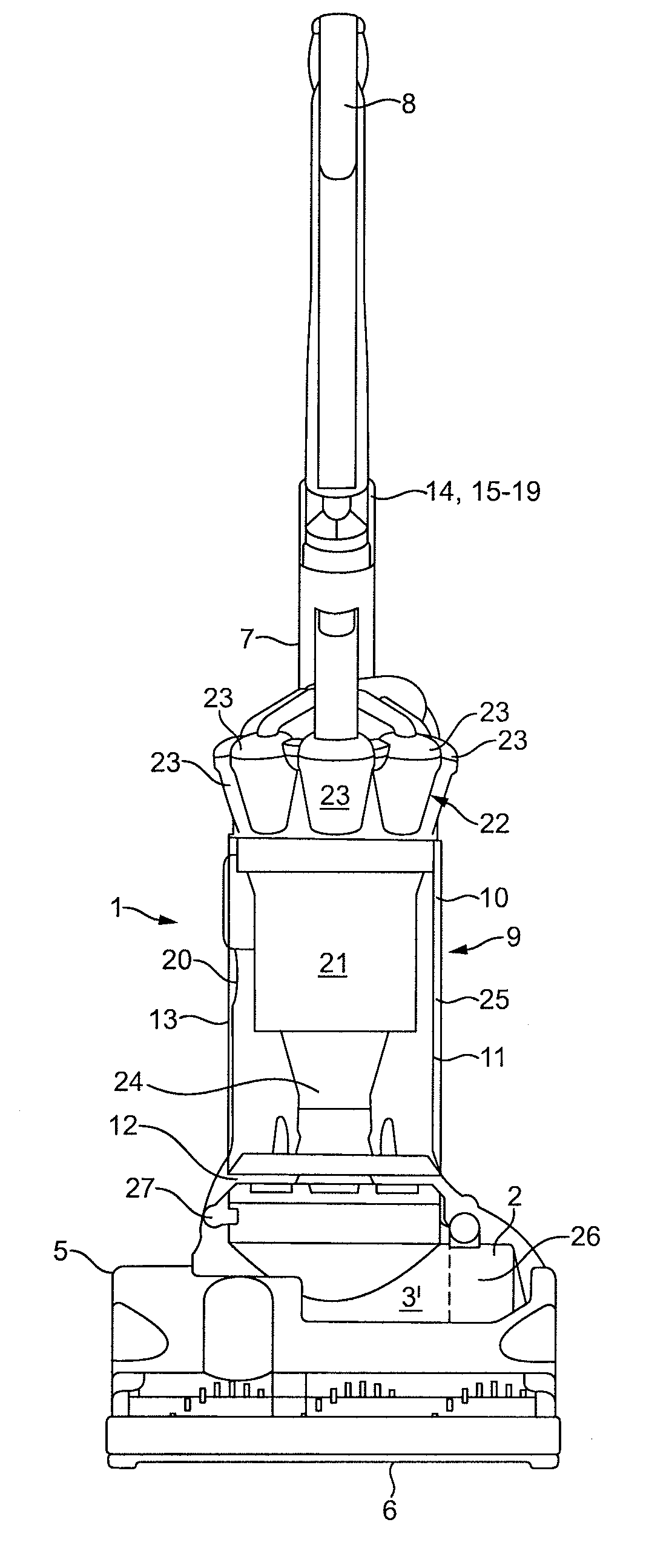
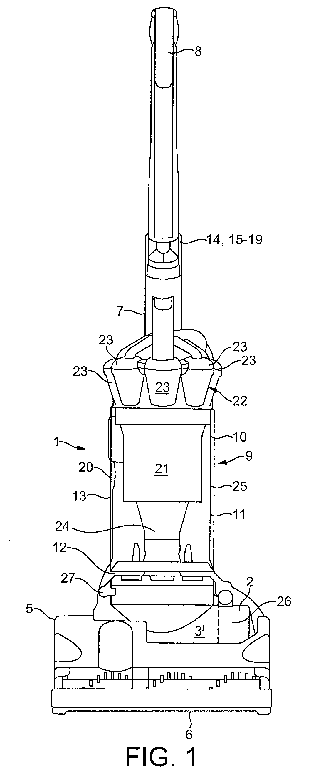
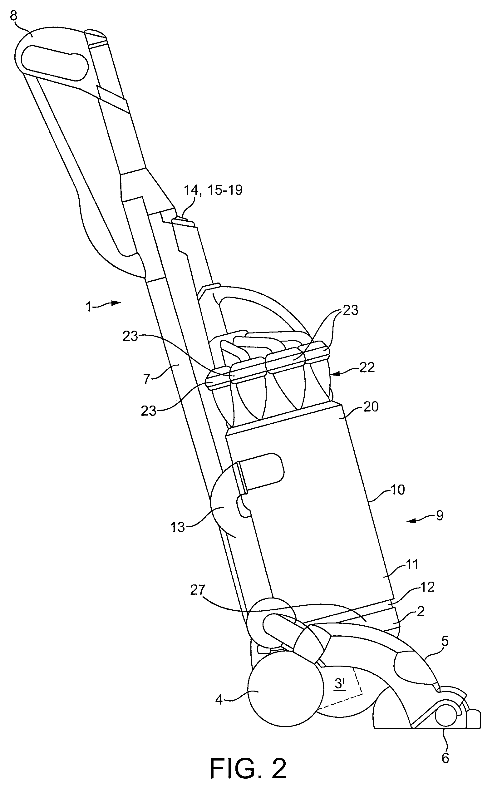
[0033]With reference to FIGS. 1 and 2, a surface treating appliance in the form of an upright vacuum cleaner is shown and indicated generally by the reference numeral 1. The vacuum cleaner 1 comprises a main body 2 which includes a main motor 3 housed in a motor and fan unit 3′ and a pair of wheels 4. A surface treating head assembly in the form of cleaner head assembly 5 is pivotably mounted on the lower end of the main body 2 and a dirty air inlet 6 is provided in the underside of the cleaner head assembly 5 facing the floor surface. The main body 2 further includes a spine 7 which extends vertically upward and merges into a hand grip 8. The hand grip 8 can be manipulated by a user to manoeuvre the vacuum cleaner 1 across a floor surface. FIG. 2 shows the upright vacuum cleaner 2 being used to clean a floor surface. The main body 2 has been reclined by the user, who employs the hand grip 8 to manoeuvre ...


PUM


Abstract

A surface treating head assembly for an appliance such as a vacuum cleaner includes a head and a piston assembly operable to apply a force to the head. The piston assembly is connected to the main motor of the vacuum cleaner by a valve. When the valve is opened, suction airflow flows through tubes connecting the motor to the piston assembly. The resulting suction force causes the piston assembly to contract, thereby drawing the cleaner head downwards. Thus, the head is urged towards the floor surface so as to improve the efficiency of a cleaning operation.

Description

REFERENCE TO RELATED APPLICATIONS[0001]This application claims the priority of United Kingdom Application No. 0901792.2, filed Feb. 4, 2009, the entire contents of which are incorporated herein by reference.FIELD OF THE INVENTION[0002]The present invention relates to a surface treating head assembly for a surface treating appliance such as a vacuum cleaner.BACKGROUND OF THE INVENTION[0003]An upright vacuum cleaner typically comprises a main body containing dirt and dust separating apparatus, a cleaner head pivotably mounted on the main body and having a dirty air inlet, and a motor and fan unit for drawing dirty air into the dirt and dust separating apparatus via the dirty air inlet so that dirt and dust can be separated from the airflow before the clean air is expelled to the atmosphere. The dirty-air inlet or suction opening through which dirty air is sucked into the vacuum cleaner is directed downwardly so that it faces the floor to be cleaned. The dirt and dust separating appara...

Claims


Application Information

Patent Timeline
Patent Type & Authority Patents(United States)
IPC IPC(8): A47L5/00
CPCA47L5/34A47L9/0494A01D34/00A01G3/06A47L7/04A47L9/02A47L9/04A47L11/40E01C23/16E01C23/24
Inventor MAGUIRE, SCOTT ANDREWDAWSON, PAULWILSON, MATTHEW CHARLES EDWARD
Owner DYSON TECH LTD
Why Eureka
Try Eureka