Assembling structure of clip and mounting member

a technology of mounting member and assembly structure, which is applied in the direction of machine supports, snap fasteners, buckles, etc., can solve the problems of deteriorating working properties, difficult to simultaneously position the leg portions of clips, and permanent deformation of flanges with age, so as to achieve easy retraction

Inactive Publication Date: 2013-08-20
PIOLAX CO LTD
View PDF24 Cites 21 Cited by
  • Summary
  • Abstract
  • Description
  • Claims
  • Application Information

AI Technical Summary

Benefits of technology

[0011]An object of the present invention is to provide an assembling structure of a clip and a mounting member capable of holding the clip at a given position with respect to a mounting seat by suppressing a permanent deformation of a flange portion of the clip and maintaining an elastic force of the flange portion.

Problems solved by technology

However, when the plural clips are respectively variously deviated in their play ranges, it is difficult to simultaneously position the leg portions of the clips so as to be inserted into the corresponding mounting holes.
Accordingly, the working property is deteriorated.
Therefore, there is a possibility that the flange is permanently deformed with age and the elastic force of the flange is lowered and a centering action of the clip is deteriorated.

Method used


Image

  • Assembling structure of clip and mounting member
  • Assembling structure of clip and mounting member
  • Assembling structure of clip and mounting member

Examples


Embodiment Construction

[0038]Referring to FIGS. 1 to 6, an assembling structure of a clip and a mounting member according to an embodiment of the present invention will be explained.

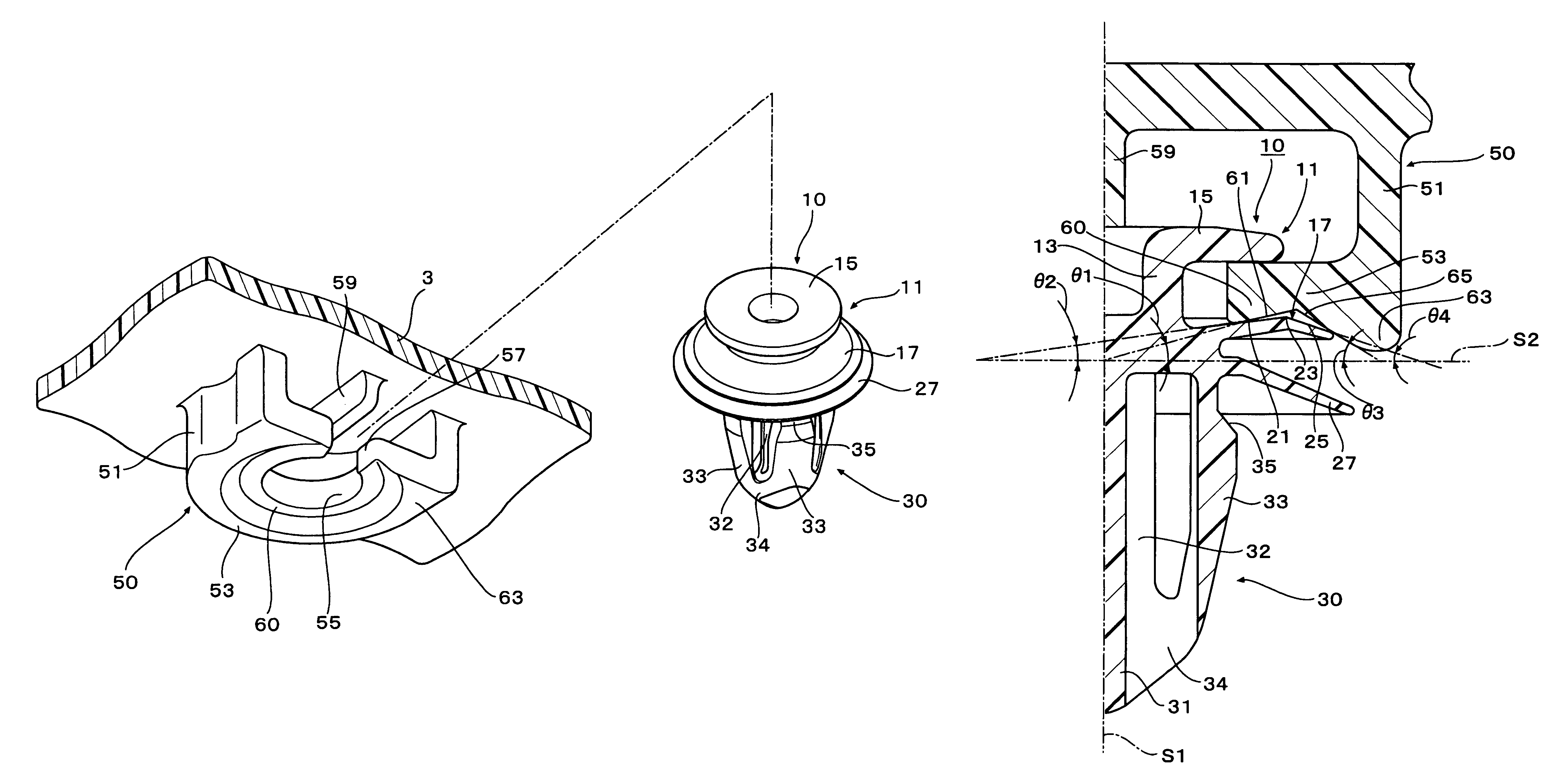
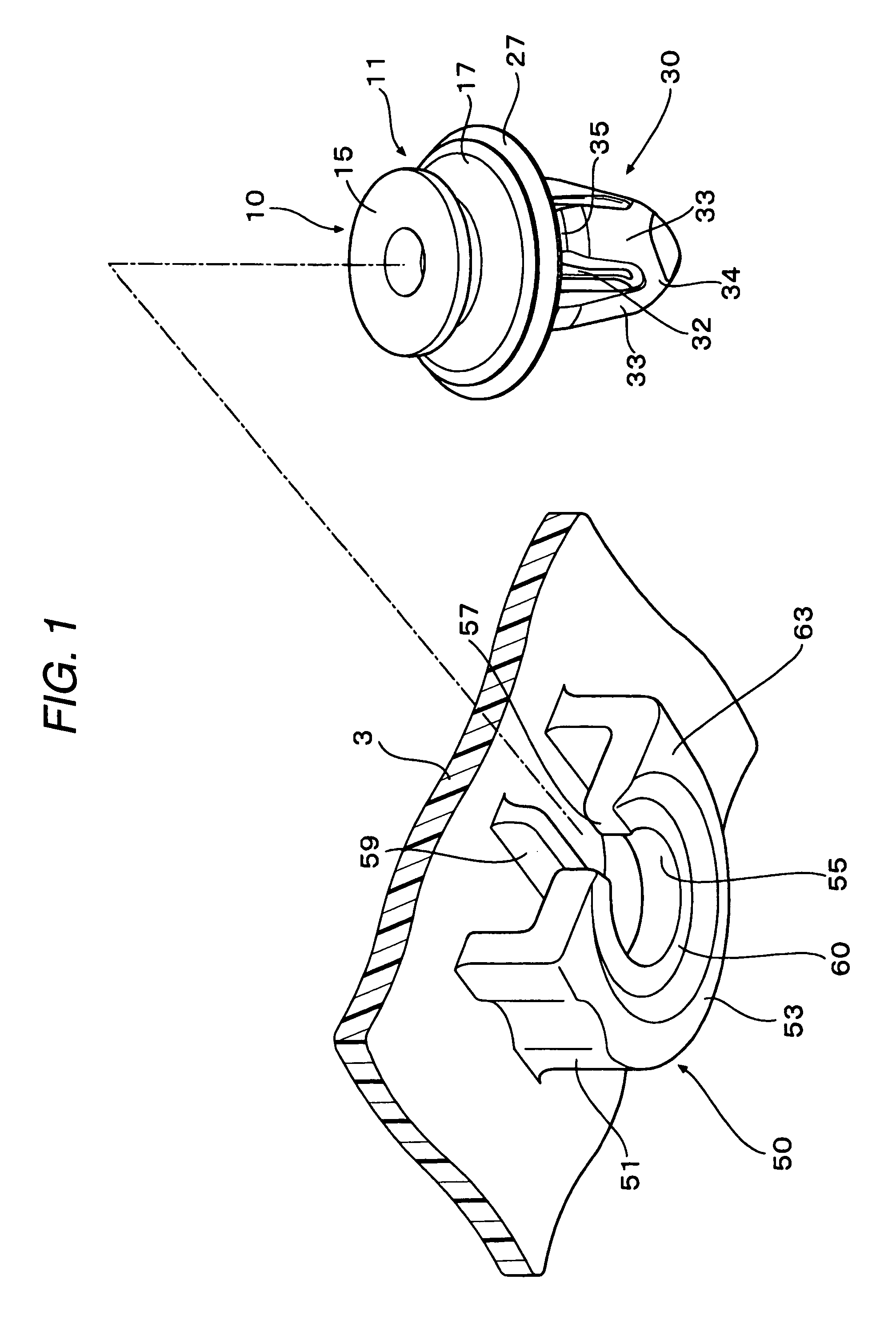
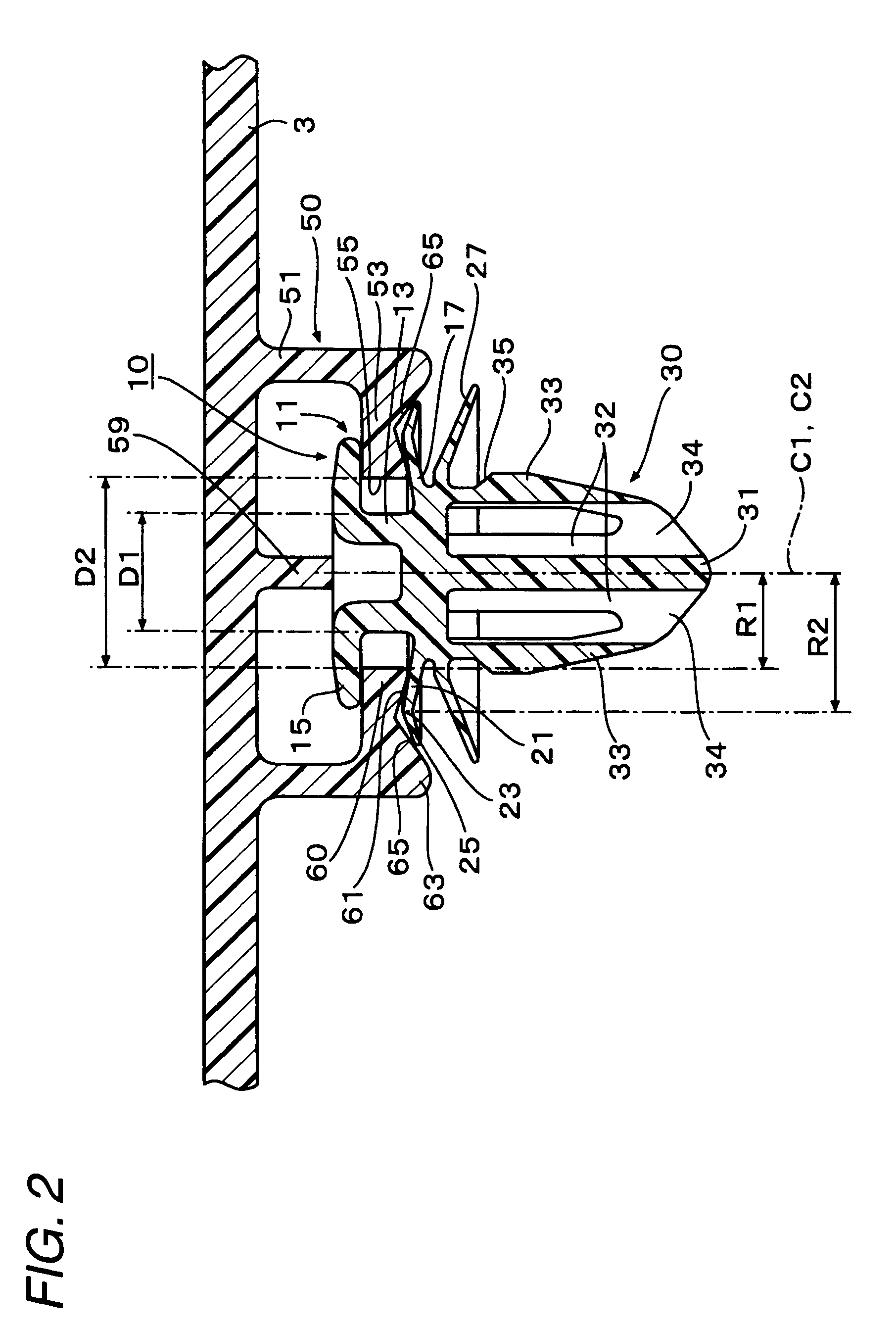
[0039]As shown in FIG. 6, when the mounting member 3 such as a garnish or a trim board is mounted on the mounted-side member 5 such as a vehicle body panel of an automobile, the clip 10 having a head portion 11 and a leg portion 30 is used. The head portion 11 of the clip 10 is inserted into the plate-like mounting seat 53 formed on the mounting member 3. When the leg portion 30 of the clip 10 is inserted into the mounting hole 7 formed in the mounted-side member 5, the mounting member 3 is mounted on the mounted-side member 5 through the clip 10. In the embodiment, an assembling structure of a clip and a mounting member, which will be simply referred to as an “assembling structure”, relates to an assembling structure of the mounting seat 53 formed on the mounting member 3 and the clip 10.

[0040]First, referring to FIGS. 1 to 3...


PUM


Abstract

According to an aspect of the present invention, there is provided an assembling structure including: a mounting member having a mounting seat; and a clip having a head and a leg. The head includes: a neck portion; and first and second flanges outwardly protrudes therefrom to sandwich the mounting seat therebetween, wherein the mounting seat includes: a hole having a diameter larger than that of the neck portion; a groove formed to communicate the hole with outside the mounting seat; and a projection protruding from a peripheral edge of the hole, wherein the second flange includes: an inner face radially-outwardly extending therefrom to gradually come close to the first flange; a top portion; and an outer face further extending to gradually separate from the first flange, and wherein the inner face abuts the projection in an assembled state.

Description

CROSS-REFERENCE TO RELATED APPLICATIONS[0001]This application claims priority from Japanese Patent Application No. 2008-048285 filed on Feb. 28, 2008, the entire contents of which are incorporated herein by reference.BACKGROUND OF THE INVENTION[0002]1. Field of the Invention[0003]An aspect of the present invention relates to an assembling structure of a clip and a mounting member, wherein the clip fixes the mounting member to a member on which the mounting member is to be mounted.[0004]2. Description of the Related Art[0005]For example, to fix a mounting member such as a trim board to a mounted-side member such as a vehicle body panel of an automobile, a clip having a head portion and a leg portion is used. In this case, a hood-like mounting seat, to which the head portion of the clip is assembled, is formed in the mounting member. The head portion of the clip is assembled to the mounting seat and the leg portion is inserted into a mounting hole of the member on which the mounting m...

Claims


Application Information

Patent Timeline
Patent Type & Authority Patents(United States)
IPC IPC(8): A47G1/10A44B17/00A44B11/25
CPCB60R13/0206F16B5/0628F16B21/086Y10T24/45995Y10T24/309
Inventor KATO, KOUICHISHINOZAKI, NOBUYANAKAZATO, HIROSHI
Owner PIOLAX CO LTD
Why Eureka
Try Eureka