Anisotropic conductive connector and production method therefor and inspection unit for circuit device

a technology of anisotropic conductive connectors and inspection units, which is applied in the direction of connecting contact material, manufacturing tools, instruments, etc., can solve the problems of difficult to achieve the necessary electrical connection to the circuit device, conductive path-forming parts conductivity is lowered, and metallic electrode structures are difficult to achieve. achieve the effect of ensuring the conductivity, stable conductivity and stably retained

Active Publication Date: 2007-03-13
ISC CO LTD
View PDF18 Cites 18 Cited by
  • Summary
  • Abstract
  • Description
  • Claims
  • Application Information

AI Technical Summary

Benefits of technology

[0042]According to the anisotropically conductive connectors of the present invention, the reinforcing material formed of insulating mesh or nonwoven fabric is contained in the surface layer portion on one surface side of the anisotropically conductive film, so that the anisotropically conductive connectors can inhibit permanent deformation by the contact of the target electrodes to be connected with pressure and deformation by abrasion from occurring even if the target electrodes to be connected are those projected. In addition, since the reinforcing material is not present at other portions than the surface layer portion on one surface side of the anisotropically conductive film, the elasticity that the elastic polymeric substance itself forming the anisotropically conductive film has is fully exhibited when the conductive path-forming parts are pressurized. As a result, necessary conductivity can be surely achieved. Accordingly, stable conductivity can be achieved over a long period of time even when the conductive path-forming parts are pressed repeatedly by the target electrodes to be connected.
[0043]Since the permanent deformation of the conductive path-forming parts by the contact of the target electrodes to be connected with pressure is small, and the elastic force thereof is stably retained over a long period of time, adhesion of the object of connection can be surely prevented or inhibited.
[0044]Since the particles exhibiting neither conductivity nor magnetism are contained in the surface layer portion on one surface side, whereby the hardness of the surface layer portion on one surface side is increased. Therefore, occurrence of the permanent deformation by the contact of the target electrodes to be connected with pressure and deformation by abrasion can be more inhibited, and moreover the migration of the electrode material to the conductive particles in the anisotropically conductive film is prevented or inhibited, so that more stable conductivity can be achieved over a long period of time, and the anisotropically conductive connector can be prevented or inhibited from adhering to a circuit device even when it is used in a state brought into contact under pressure with the circuit device under a high-temperature environment in the electrical inspection of the circuit device.
[0045]According to the production process of the anisotropically conductive connector of the present invention, the molding material layer containing the reinforcing material, formed on the molding surface of one face and the molding material layer formed on the molding surface of the other face are stacked, and the respective molding material layers are subjected to a curing treatment in this state, so that an anisotropically conductive connector having a anisotropically conductive film containing the reinforcing material at only the surface layer portion on one surface side can be advantageously and surely produced.
[0046]According to the inspection apparatus for circuit devices of the present invention, the above-described anisotropically conductive connector is provided, so that occurrence of permanent deformation by the contact of electrodes to be inspected with pressure and deformation by abrasion is inhibited even if the electrodes to be inspected are those projected, and so stable conductivity can be achieved over a long period of time even when inspection is conducted continuously as to a great number of circuit devices, and moreover the fact that the circuit device adheres to the anisotropically conductive connector can be surely prevented or inhibited.
[0047]According to the inspection apparatus for circuit devices of the present invention, since the use of sheet-like connector in addition to the anisotropically conductive connector becomes unnecessary, positioning between the anisotropically conductive connector and the sheet-like connector is unnecessary, so that the problem of positional deviation between the sheet-like connector and the anisotropically conductive connector due to temperature change can be avoided, and moreover the constitution of the inspection apparatus becomes easy.

Problems solved by technology

However, the following problems are involved when a conventional anisotropically conductive sheet is used as a connector in electrical inspection of a circuit device having protruding electrodes composed of, for example, a solder such as solder ball electrodes.
As a result, a problem that the conductivity of the conductive path-forming parts is lowered arises.
In the jig for inspection of circuit devices, however, it is difficult to achieve necessary electrical connection to the circuit device, which is the object of inspection, when the pitch of the electrodes to be inspected of the circuit device is small, i.e., the pitch of the metallic electrode structures in the sheet-like connector is small.
Therefore, the metallic electrode structures in the sheet-like connector cannot be surely brought into contact with all the electrodes to be inspected in the circuit device, which is the object of inspection, when the circuit device is such that the surface accuracy of a substrate thereof is low, the evenness of thickness of the substrate is low, or a scatter of height of the electrodes to be inspected is wide.
As a result, good electrical connection to such a circuit device cannot be achieved.
Even if a good electrically connected state to all the electrodes to be inspected can be achieved, considerably great pressing force is required to bring the metallic electrode structures into contact under pressure with the electrodes to be inspected, so that the following problems are involved.
The whole inspection apparatus including a pressing mechanism for bringing the metallic electrode structures into contact under pressure with the electrodes to be inspected becomes a large scale, the production cost of the whole inspection apparatus becomes high, and moreover considerably great pressing force is applied to the anisotropically conductive sheet, whereby the service life of the anisotropically conductive sheet becomes short.
As a result, it is difficult to stably retain the good electrically connected state.
It is also necessary to fix these members in a state aligned to each other, so that the production cost of the whole apparatus necessary for the inspection becomes high.
Further, conventional anisotropically conductive sheets involve the following problems.
When permanent deformation is caused on the conductive path-forming parts in the anisotropically conductive sheet by bringing them into contact under pressure with the protruding electrodes and the elastic force of the conductive path-forming parts is lowered, the circuit device is not easily separated from the anisotropically conductive sheet, so that the work of exchanging the circuit device after completion of the inspection to an uninspected circuit device cannot be smoothly conducted.
As a result, inspection efficiency of circuit devices is lowered.
When the anisotropically conductive sheet adheres to the circuit device in great strength in particular, it is difficult to separate the circuit device from the anisotropically conductive sheet without damaging the anisotropically conductive sheet.
Therefore, such an anisotropically conductive sheet cannot be used in the following inspection.

Method used


Image

  • Anisotropic conductive connector and production method therefor and inspection unit for circuit device
  • Anisotropic conductive connector and production method therefor and inspection unit for circuit device
  • Anisotropic conductive connector and production method therefor and inspection unit for circuit device

Examples


example 1

(a) Production of Supporting Body and Mold:

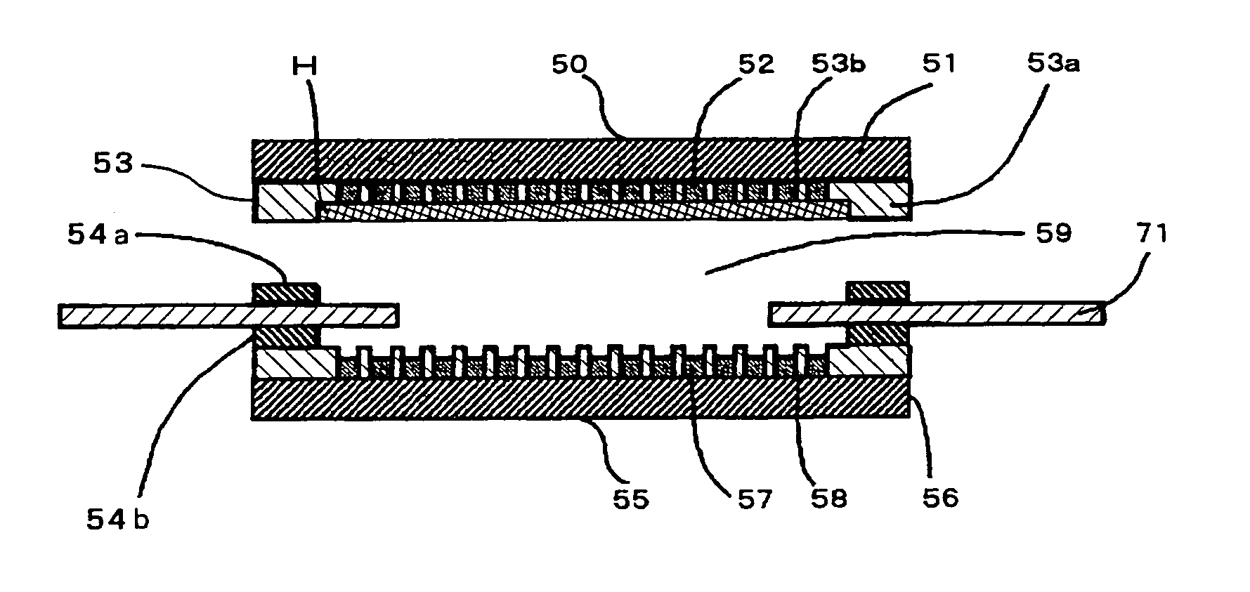
[0235]A supporting body of the following specification was produced in accordance with the construction shown in FIG. 4, and a mold of the following specification for molding an anisotropically conductive film was produced in accordance with the construction shown in FIG. 6.

[Supporting Body]

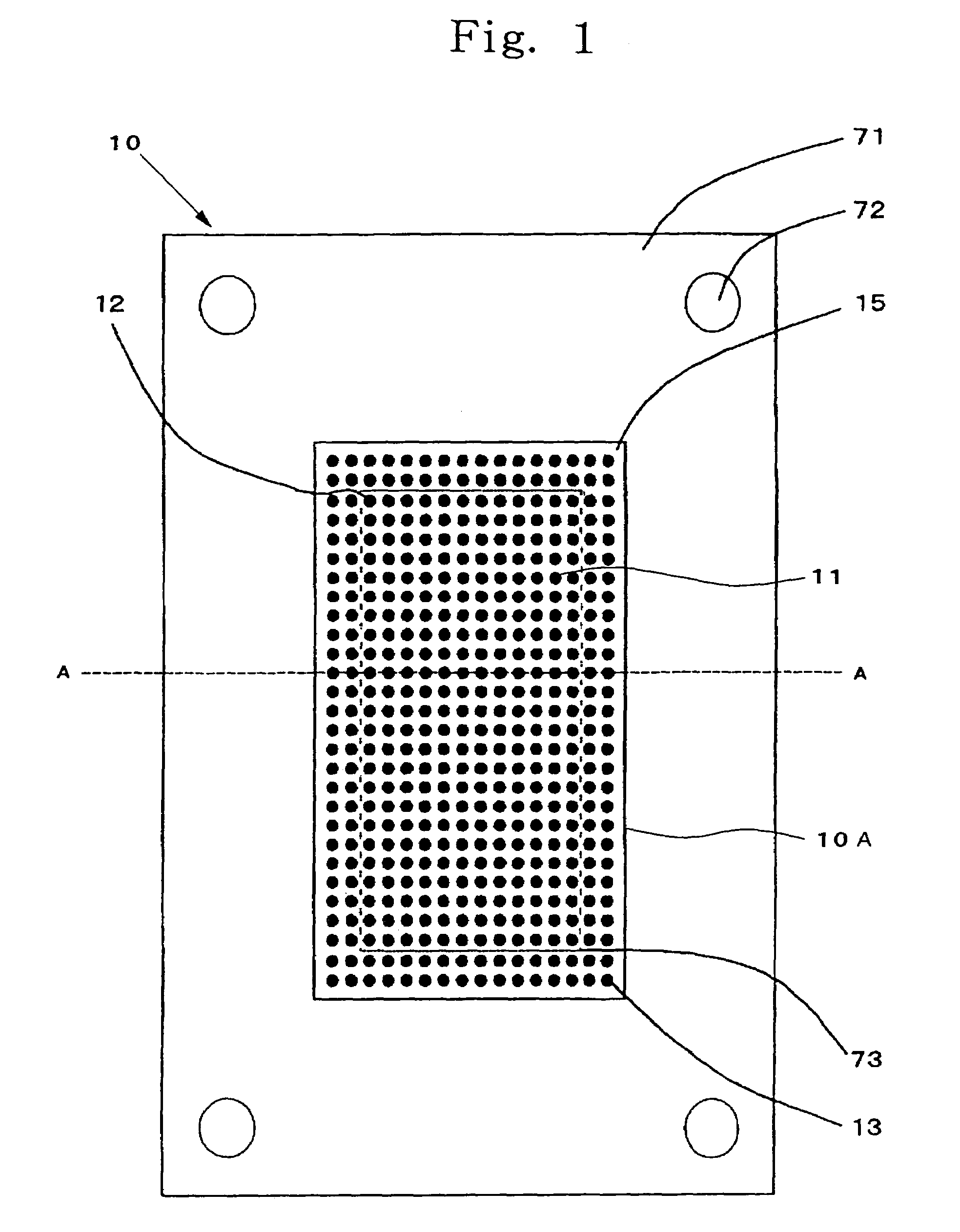
[0236]The supporting body (71) is such that its material is SUS304, the thickness is 0.1 mm, the size of an opening (73) is 17 mm×10 mm, and positioning holes (72) are provided at 4 corners.

[Mold]

[0237]Ferromagnetic substance substrates (51, 56) of both top face (50) and bottom face (55) are such that their materials are iron, and the thickness is 6 mm.

[0238]Ferromagnetic substance layers (52, 57) of both top face (50) and bottom face (55) are such that their materials are nickel, the diameter is 0.45 mm (circular), the thickness is 0.1 mm, the arrangement pitch (center distance) is 0.8 mm, and the number of the ferromagnetic substance layers in each fac...

example 2

(a) Production of Supporting Body and Mold:

[0266]A supporting body of the following specification was produced in accordance with the construction shown in FIG. 4, and a mold of the following specification for molding an anisotropically conductive film was produced in accordance with the construction shown in FIG. 6 except that non-magnetic substance layers of a top face had an even thickness, and no recess was formed in the surface of the top face.

[Supporting Body]

[0267]The supporting body (71) is such that its material is SUS304, the thickness is 0.15 mm, the size of an opening (73) is 17 mm×10 mm, and positioning holes (72) are provided at 4 corners.

[Mold]

[0268]Ferromagnetic substance substrates (51, 56) of both top face (50) and bottom face (55) are such that their materials are iron, and the thickness is 6 mm.

[0269]Ferromagnetic substance layers (52, 57) of both top face (50) and bottom face (55) are such that their materials are nickel, the diameter is 0.45 mm (circular), the ...

example 3

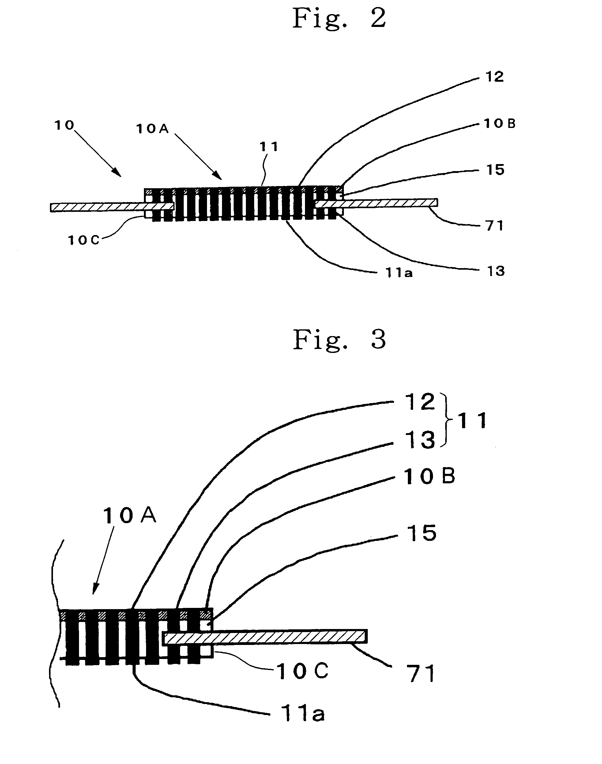
[0279]An anisotropically conductive connector (10) according to the present invention was produced in the same manner as in Example 2 except that the spacer (54a) arranged on the molding surface of the top face (50) was changed to that having a thickness of 0.1 mm, and the spacer (54b) arranged on the molding surface of the bottom face (55) was changed to that having a thickness of 0.1 mm. The anisotropically conductive film (10A) in the resultant anisotropically conductive connector (10) is in a form of a rectangle having dimensions of 20 mm by 13 mm, wherein the thickness of conductive path-forming parts (11) is 0.40 mm, the thickness of insulating parts (15) is 0.35 mm, the number of conductive path-forming parts (11) is 288 (12×24), the diameter of each conductive path-forming part (11) is 0.45 mm, and the arrangement pitch (center distance) of the conductive path-forming parts (11) is 0.8 mm. Further, a ratio r1 / r2 of the opening diameter of the mesh to the average particle dia...


PUM

PropertyMeasurementUnit
diameter r2aaaaaaaaaa
diameter r1aaaaaaaaaa
opening diameteraaaaaaaaaa

Abstract

An anisotropically conductive connector, inhibits permanent deformation by contact of target electrodes to be connected with pressure and deformation by abrasion from occurring even if the target electrodes to be connected are those projected, achieves stable conductivity over a long period of time even when it is pressed repeatedly, and prevents or inhibits an object of connection from adhering, a production process thereof, and an inspection apparatus for circuit devices equipped with the anisotropically conductive connector. The anisotropically having an anisotropically conductive film, in which a plurality of conductive path-forming parts each extending in a thickness-wise direction of the film are arranged in a state mutually insulated by insulating parts. The anisotropically conductive film is formed by an insulating elastic polymeric substance, conductive particles exhibiting magnetism are contained in the conductive path-forming parts, and a reinforcing material formed of insulating mesh or nonwoven fabric is contained in a surface layer portion on one surface side of the anisotropically conductive film.

Description

TECHNICAL FIELD[0001]The present invention relates to an anisotropically conductive connector suitable for use in, for example, inspection of circuit devices such as semiconductor integrated circuits and a production process thereof, and an inspection apparatus for circuit devices, which is equipped with this anisotropically conductive connector, and particularly to an anisotropically conductive connector suitable for use in inspection of circuit devices such as semiconductor integrated circuits having protruding electrodes such as solder ball electrodes and a production process thereof, and an inspection apparatus for circuit devices.BACKGROUND ART[0002]An anisotropically conductive sheet is a sheet exhibiting conductivity only in its thickness-wise direction or having pressure-sensitive conductive conductor parts exhibiting conductivity only in the thickness-wise direction when they are pressed in the thickness-wise direction. Since the anisotropically conductive sheet has such fe...

Claims


Application Information

Patent Timeline
Patent Type & Authority Patents(United States)
IPC IPC(8): G01R1/073H01R43/00H01R11/01
CPCH01R11/01Y10T29/49117Y10T29/53196H01R13/03
Inventor YAMADA, DAISUKEKIMURA, KIYOSHI
Owner ISC CO LTD
Why Eureka
Try Eureka