Stemless shoulder implant

a stemless, shoulder technology, applied in the field of humerus implants, can solve the problems of increasing the removal torque with time, and achieve the effects of decreasing the insertion torque, increasing stability, and decreasing the thickness of the fins

Active Publication Date: 2013-08-20
ARTHREX
View PDF11 Cites 52 Cited by
  • Summary
  • Abstract
  • Description
  • Claims
  • Application Information

AI Technical Summary

Benefits of technology

[0007]In an embodiment the humerus implant has a cup shaped body (10) having side walls between a top side (11) and a bottom side (12). At the outside of the body is a thread (13) having a plurality of fins starting with a first fin (14) and ending with a last fin (15). There are cutouts (16) between the fins. The fins are specifically designed to secure the body within the bone (30) even without cementing. Due to the radial anchoring in the bone material the fins cause a comparatively high pull out force of the implant. At least one fin, preferably a plurality of fins, most preferably all fins have an inclined leading surface (21) which helps in incising into the bone by rotating the body in an inward direction. By this measure the insertion torque is minimized. The inclination of the leading surface (21) may also be negative resulting in an undercut leading surface (21). There may be a combination of different types of fins in one thread. Furthermore at least one fin, preferably a plurality of fins, most preferably all fins have a forward oriented undercut trailing surface (25). This results in an angle of less than 90 degrees between a top surface (23) and the trailing surface (25), blocking rotation in the opposite, outward direction. Therefore the removal torque is maximized. Between the individual fins there are cutouts leaving room for abraded bone material and therefore further reducing the insertion torque and avoiding chattering. Tests have proven that this thread design results in removal torques similar to and preferably at least 60% of insertion torques immediately after insertion and without any recovery period allowing further bone growth into the structure. Due to such bone growth the removal torque increases further with time.
[0019]In the most preferred embodiment it is designed to provide a combination interface for a joint adapter to interface with the glenoid component of a reverse prosthesis and the humeral component of an anatomical prosthesis. Here specifically the cup shape allows a more simple and robust interface for the humeral component of an anatomical prosthesis, which for example may be held by a Morse taper. This embodiment allows simple replacement of an anatomical prosthesis by a reverse prosthesis during revision. Here exchanging of a prosthesis stem is no more necessary. Even the implant can remain in place, as only the heads must be exchanged.

Problems solved by technology

Due to such bone growth the removal torque increases further with time.

Method used


Image

  • Stemless shoulder implant
  • Stemless shoulder implant
  • Stemless shoulder implant

Examples


Embodiment Construction

[0041]While the invention is susceptible to various modifications and alternative forms, specific embodiments thereof are shown by way of example in the drawings and will herein be described in detail. It should be understood, however, that the drawings and detailed description thereto are not intended to limit the invention to the particular form disclosed, but on the contrary, the intention is to cover all modifications, equivalents and alternatives falling within the spirit and scope of the present invention as defined by the appended claims.

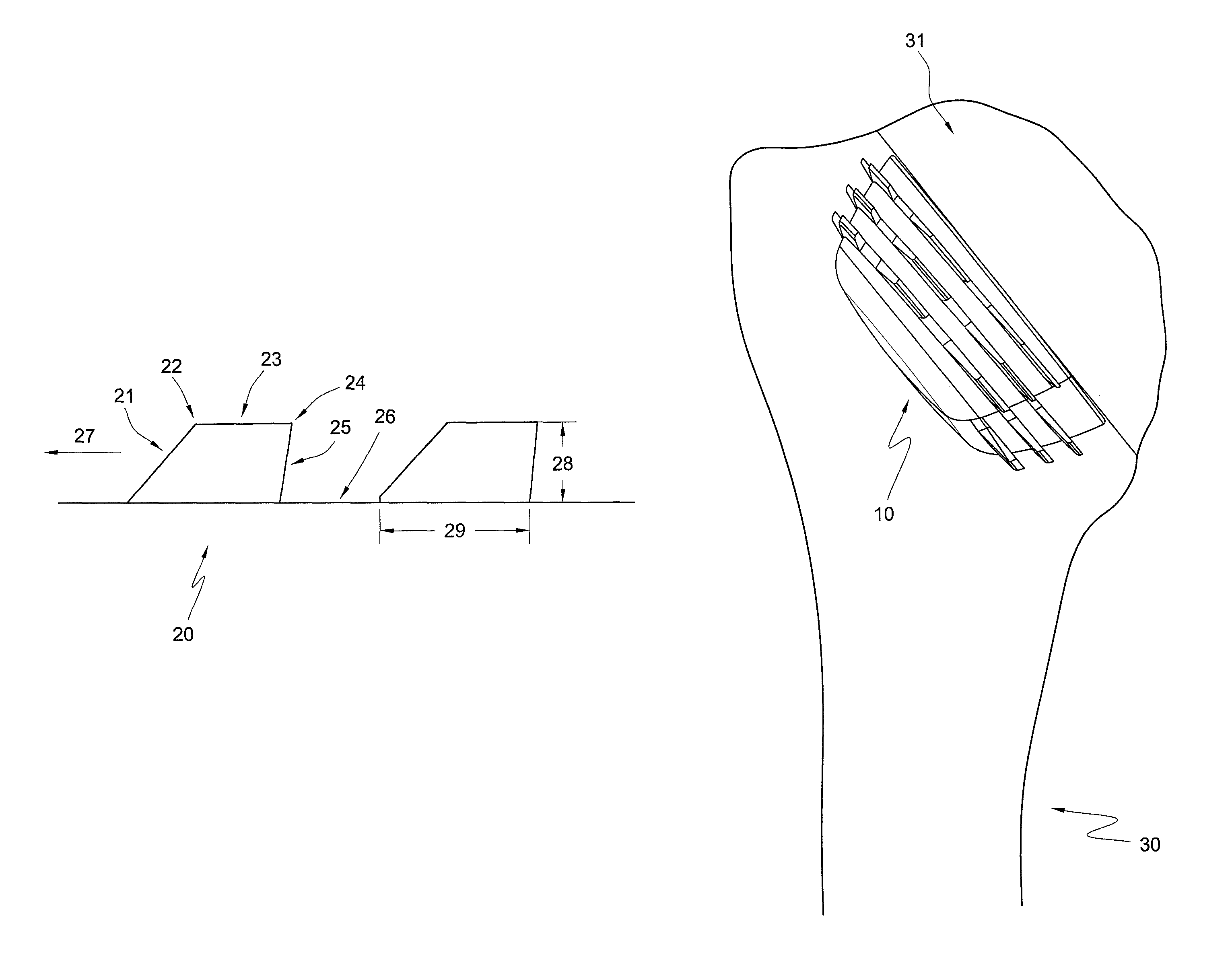
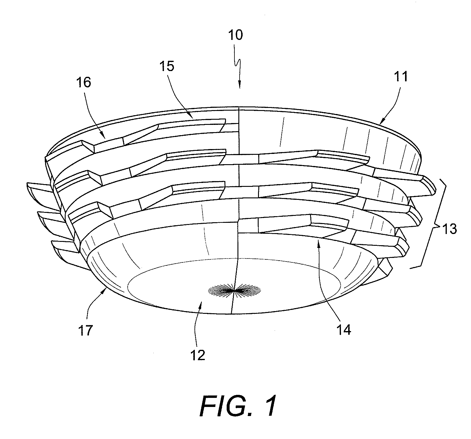
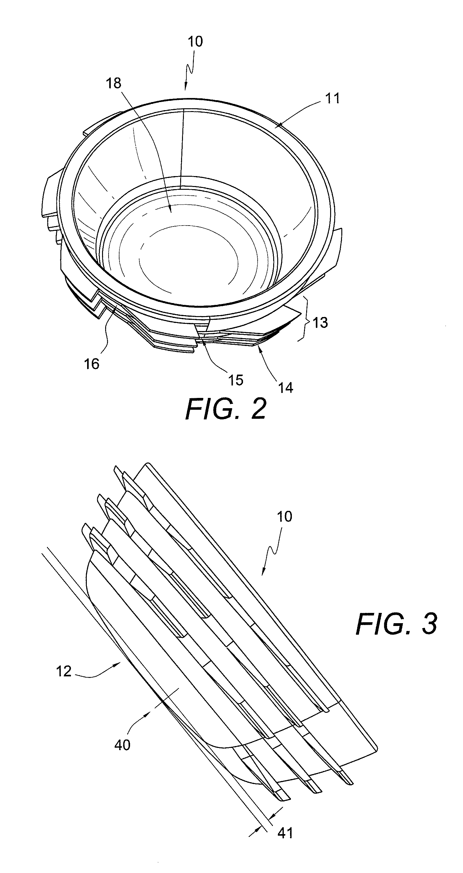
[0042]FIG. 1 shows an embodiment of a humerus implant. The implant has a cup shaped body (10) having side walls between a top side (11) and a bottom side (12). At the outside of the body is a thread (13) having a plurality of fins starting with a first fin (14) and ending with a last fin (15). There are cutouts (16) between the fins. The body may be screwed clockwise as viewed from the top side into the bone. A counter clock wise oriented thr...


PUM


Abstract

A humerus implant for a reverse shoulder prosthesis has a cup shaped body and a thread at the outside of the body. The thread has a plurality of fins with cut-outs between the fins. At least one fin has an inclined leading surface which helps in incising into the bone by rotating the body in an inward direction. Furthermore, at least one fin has a forward oriented undercut trailing surface blocking rotation in the outward direction.

Description

FIELD OF THE INVENTION[0001]The present invention relates to a shoulder arthroplasty system to surgical reconstitution of the shoulder and, in particular, to a humerus implant.BACKGROUND OF THE INVENTION[0002]The shoulder joint is a ball-and-socket joint which has an exceptional range of motion. Shoulder instability and other maladies of the shoulder joint, such as arthrosis or fracture, may require a replacement of the joint.[0003]A shoulder joint prosthesis which includes the replacement of the convex head of the humerus is disclosed in U.S. Pat. No. 7,819,923. It reflects the orientation and the center of rotation of actual joints. In the case of a worn or damaged rotator cuff or too much bone loss such a prosthesis would not recover the range of motion. In such a case a reverse shoulder prosthesis may be preferable. An example of such a prosthesis is disclosed in the U.S. patent application Publication No. 2009 / 0210065 A1. In such a prosthesis, the humeral component includes a s...

Claims


Application Information

Patent Timeline
Patent Type & Authority Patents(United States)
IPC IPC(8): A61F2/40
CPCA61F2/40A61F2/4003A61F2/4014A61F2/30771A61F2002/30331A61F2002/305A61F2002/30507A61F2002/30853A61F2002/30856A61F2002/30858A61F2002/30861A61F2002/30863A61F2002/30873A61F2002/4007A61F2002/4018A61F2002/4022A61F2002/30851
Inventor METCALFE, NICK J. T.MICHEL, GERLINDE
Owner ARTHREX
Why Eureka
Try Eureka