Measurement device

a measurement device and measurement technology, applied in the direction of measurement devices, mechanical diameter measurements, instruments, etc., can solve the problems of reducing the reliability of a read coordinate value and the process growing longer, so as to shorten the read time of the register, shorten the measurement processing time, and reduce the labor involved

Active Publication Date: 2013-08-27
MITUTOYO CORP
View PDF8 Cites 10 Cited by
  • Summary
  • Abstract
  • Description
  • Claims
  • Application Information

AI Technical Summary

Benefits of technology

[0007]In light of the phenomena described above, the present invention provides a measurement device which is able to achieve improvement in the reliability of a read coordinate value and to accelerate latch processing.
[0009]In the invention, the touch counter which counts the touch signal which detects the contact state (contoured state) of the measurement head of the probe with the measured object and the scale counter which counts the coordinate detection signal output from the coordinate detector are installed within a single integrated circuit, provided within the control circuit board which constitutes the measurement device. Here, the touch counter and the scale counter are installed within a single integrated circuit on the control circuit board. Therefore, when latch control is performed by software, for example, the latch control on each register may be omitted and the latching of the touch counter count value and the latching of the scale counter count value may be activated at the same time. Accordingly, measurement processing speed may be improved and also the position coordinates of the probe in the moment of contact of the measurement head with the measured object may be measured, and measurement accuracy may be improved.
[0011]In measurement devices, when the probe is provided so as to be interchangeable in accordance with the shape of the measured object and another probe is exchanged, the signal format of the touch signal output by the contact detector may also change. In such a case, conventionally, it was necessary to change the circuit containing the counter which counts the touch signals sent from the probe as well, which involved complicated labor. In contrast, in the present invention, the integrated circuit provided on the control circuit board is fitted with a plurality of touch counters corresponding to a plurality of touch signals which differ in their signal format. Further, when the probe is exchanged for another probe which outputs a touch signal of a different signal format, the connector shape may also have a different shape; however, the control circuit board is provided with a plurality of connectors corresponding to the touch signals of different signal formats. In a structure such as in the present invention, even when the probe is exchanged for a probe of a different type, the touch signal may be output to the control circuit board by the probe connecting to the connector which corresponds to the signal format of the exchanged probe. In the integrated circuit of the control circuit board, since a plurality of touch counters are provided corresponding to a plurality of signal formats, even when the probe is exchanged, the touch signal may be processed without exchanging the integrated circuit or the like. Therefore, it is possible to lessen the labor involved in exchanging the probe in the measurement device.
[0012]In the present invention, because the touch counter and the scale counter are both installed on a single integrated circuit, the measurement device is able to shorten the read time of the registers and is able to make the latch processing of the touch counter count value and the latch processing of the scale counter count value simultaneous. Accordingly, the measurement processing time may be shortened and measurements may be carried out with a high degree of accuracy.

Problems solved by technology

When such a time lag occurs, there are phenomena such as the processing time for carrying out a measurement process growing longer, or that reliability of a read coordinate value may decline due to the latch timing of the scale counter and the latch timing of the touch counter differing.

Method used


Image

  • Measurement device
  • Measurement device
  • Measurement device

Examples


Embodiment Construction

[0018]The particulars shown herein are by way of example and for purposes of illustrative discussion of the embodiments of the present invention only and are presented in the cause of providing what is believed to be the most useful and readily understood description of the principles and conceptual aspects of the present invention. In this regard, no attempt is made to show structural details of the present invention in more detail than is necessary for the fundamental understanding of the present invention, the description is taken with the drawings making apparent to those skilled in the art how the forms of the present invention may be embodied in practice.

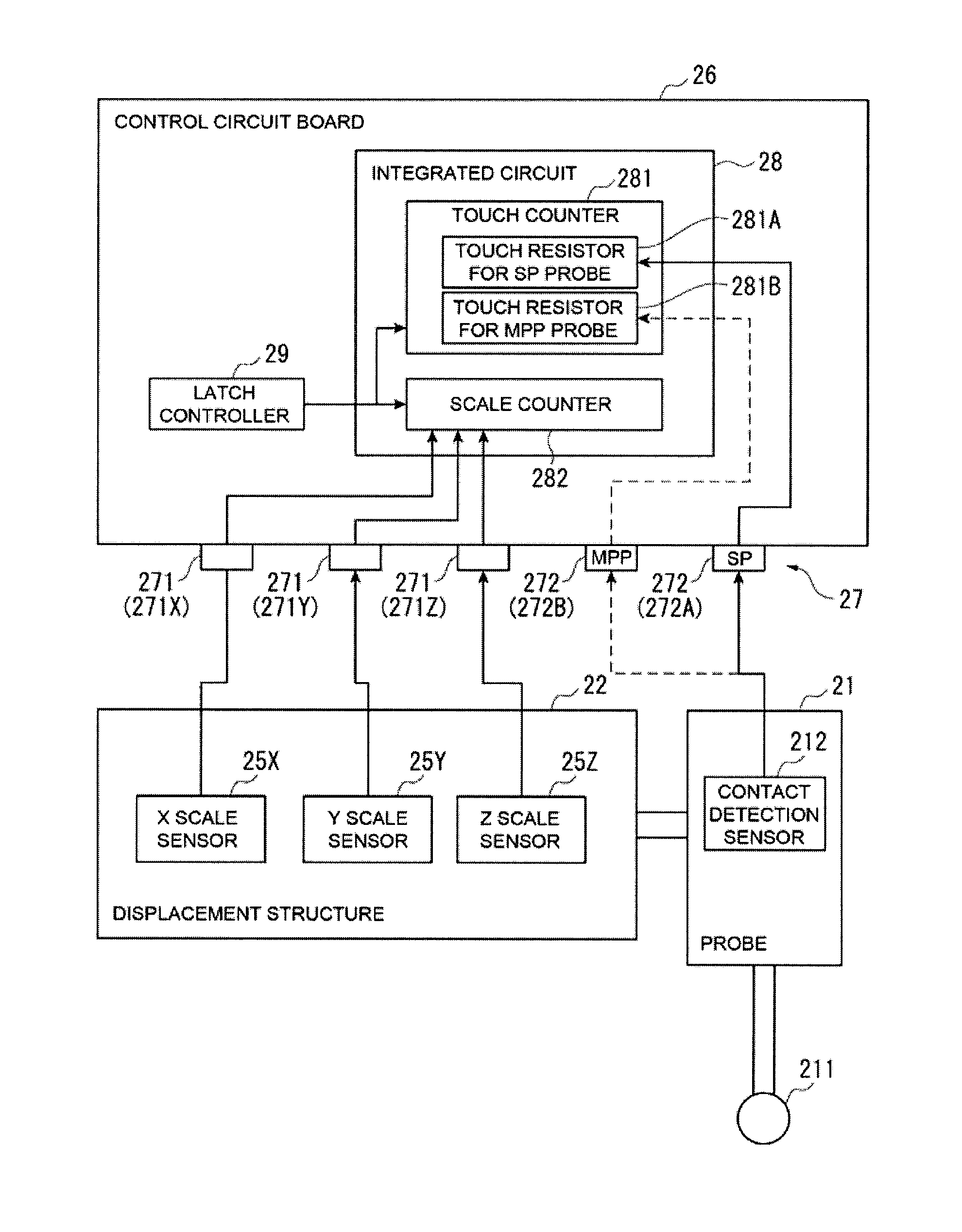
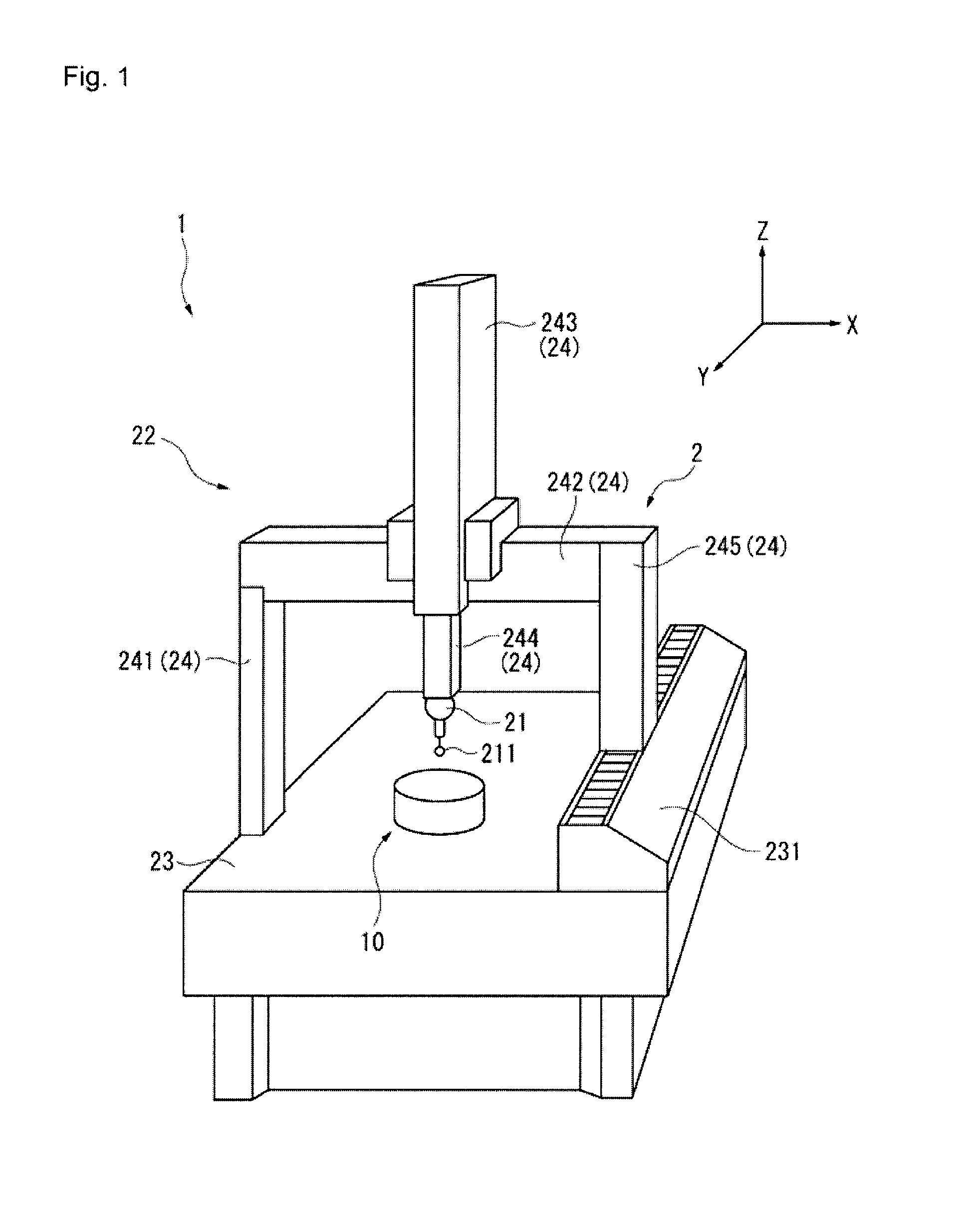
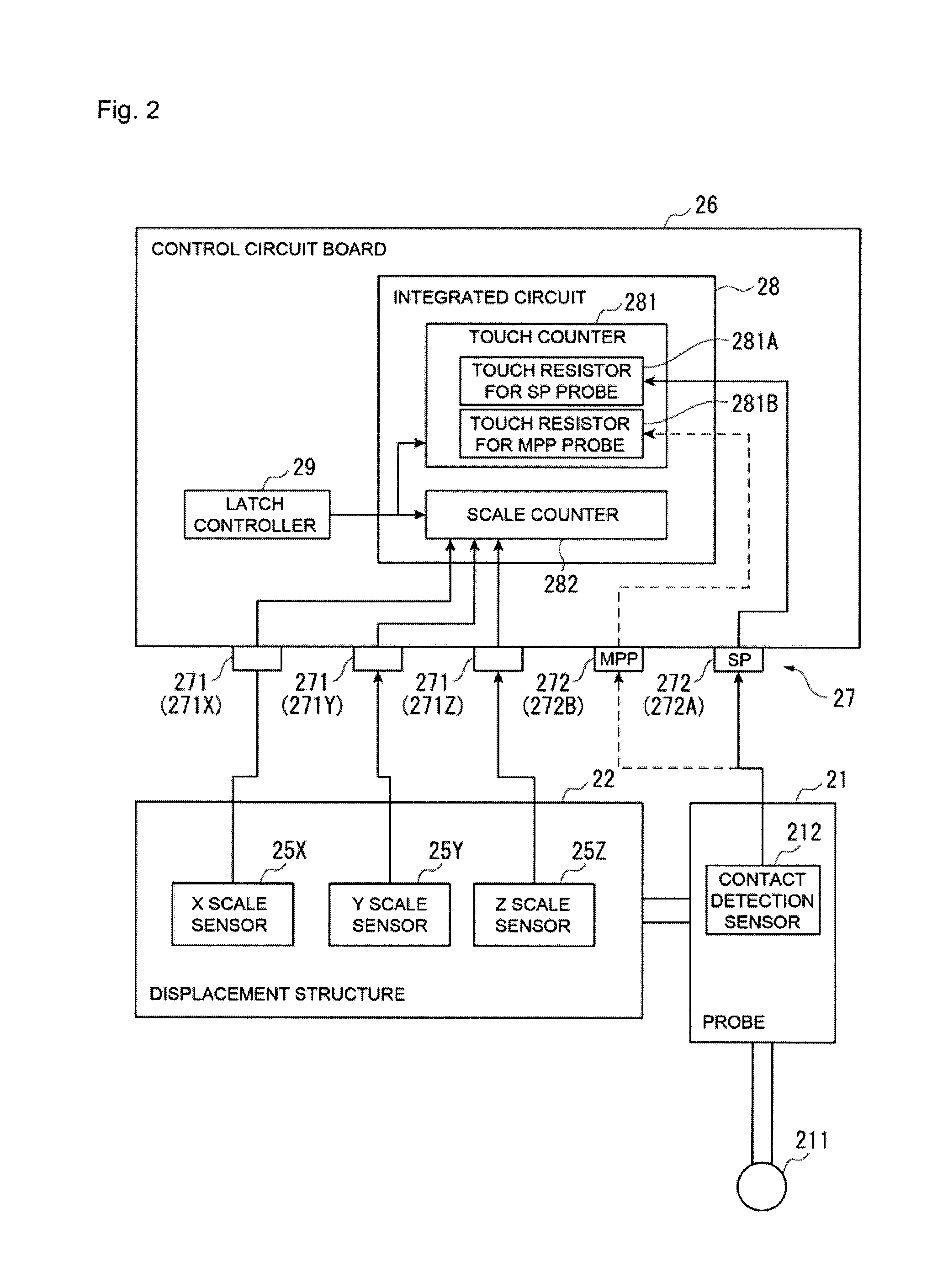
[0019]Hereafter, a three-dimensional measuring machine (measurement device) according to one embodiment of the present invention is described based on the figures. Hereafter, an embodiment of the present invention is described based on the figures. FIG. 1 illustrates an overview structure for the three-dimensional measuring ma...


PUM


Abstract

A three-dimensional measuring machine (measurement device) which supplies a probe having a measurement head able to make contact with a measured object and a contact detection sensor which detects the contact of a measurement head with a measured object and outputs a touch signal; a displacement structure which displaces a probe along three axial directions orthogonal to one another; scale sensors which detect the position coordinates of a probe and output a coordinate detection signal; a control circuit board having an integrated circuit on which are installed a touch counter which counts touch signals and a scale counter which counts coordinate detection signals; and a latch controller which latches a touch counter value and a scale counter value at the same time.

Description

CROSS-REFERENCE TO RELATED APPLICATIONS[0001]The present application claims priority under 35 U.S.C. §119 of Japanese Application No. 2010-197594 filed on Sep. 3, 2010, the disclosure of which is expressly incorporated by reference herein in its entirety.BACKGROUND OF THE INVENTION[0002]1. Field of the Invention[0003]The present invention relates to a measurement device having a probe which makes contact with a measured object and having a displacement structure which is capable of displacing the probe in a predetermined axial direction.[0004]2. Description of Related Art[0005]Conventionally, measurement devices such as a three-dimensional measuring machine have been known which measure the shape or the like of a measured object by displacing a probe along an axial direction (XYZ axis directions) and bringing a measurement head provided on the probe into contact with the measured object (see for example Japanese Patent Laid-Open Publication No. 2001-21303). Measurement devices of th...

Claims


Application Information

Patent Timeline
Patent Type & Authority Patents(United States)
IPC IPC(8): G01B5/008
CPCG01B21/047G01B5/12
Inventor KUMAGAI, HIDEKIMIZUKAMI, KAZUMI
Owner MITUTOYO CORP
Why Eureka
Try Eureka