

Ice cube tray and method for releasing a single cube from tray
a technology of ice cubes and cubes, which is applied in the field of ice cubes, can solve problems such as ice cubes that may break
- Summary
- Abstract
- Description
- Claims
- Application Information
AI Technical Summary
Problems solved by technology
Method used
Image

Examples
Embodiment Construction
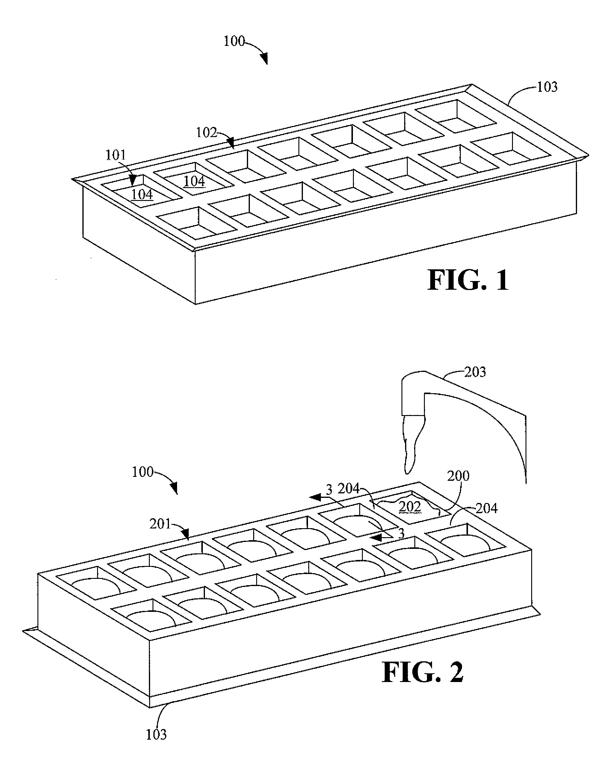
[0011]FIG. 1 is a top perspective view of an ice tray 100 in accordance with an embodiment of the present disclosure. The ice tray 100 may be made of any type of material known in the art or future-developed, including plastic or metal.
[0012]The ice tray 100 comprises a plurality of cavities 101 within a top surface 102 of the ice tray 100. The cavities 101 are shown in two rows of seven cavities 101. However, other numbers of cavities 101 are possible in other embodiments.
[0013]The ice tray 100 is used to make one or more ice cubes 104. In this regard, water (not shown) is poured into one or more of the cavities 101. The ice tray 100 is placed in a freezer (not shown), and the water freezes into the ice cubes 104. Once the ice cubes 104 are formed, a user (not shown) removes the ice tray 100 from the freezer.
[0014]The ice tray 100 further comprises a lip 103. The lip 103 is contiguous with the top side 102. Further, the lip 103 outlines the periphery of the top side 102, and the li...
PUM
| Property | Measurement | Unit |
|---|---|---|
| angle | aaaaa | aaaaa |
| force | aaaaa | aaaaa |
| angle | aaaaa | aaaaa |
Abstract
Description
Claims
Application Information