Adjustable suspension system for a work vehicle

a suspension system and work technology, applied in the field of work vehicles, can solve the problems of obstructing operator visibility, increasing the height of the hood, and limiting the steering range of motion

Active Publication Date: 2013-08-27
BLUE LEAF I P INC
View PDF16 Cites 8 Cited by
  • Summary
  • Abstract
  • Description
  • Claims
  • Application Information

AI Technical Summary

Benefits of technology

[0005]The present invention provides a suspension system including an axle configured to support a first wheel on a first lateral end of the axle, and a second wheel on a second lateral end of the axle. The suspension system also includes a steering assembly configured to rotate each wheel relative to the axle about a substantially vertical axis. In addition, the suspension system includes an actuating cylinder extending between the axle and a frame of a work vehicle. The actuating cylinder is configured to transition the frame between a lowered position that enables the steering assembly to rotate each wheel through a first range of motion without contact between the wheels and a component of the work vehicle, and a raised position that enables the steering assembly to rotate the wheels through a second range of motion without contact between the wheels and the component. The second range of motion is greater than the first range of motion. In this configuration, operator visibility is enhanced while the frame is in the lowered position due to a reduction in hood height relative to the soil surface. In addition, to accommodate increased steering angles, the frame may be temporarily transitioned toward the raised position to provide additional clearance between the wheels and the component.

Problems solved by technology

However, if a work vehicle employs larger components (e.g., engines, cooling fans, etc.), the steering range of motion may be undesirably limited.
While raising the frame relative to the axle may expand the steering range of motion, the resulting increased hood height may obstruct operator visibility.

Method used


Image

  • Adjustable suspension system for a work vehicle
  • Adjustable suspension system for a work vehicle
  • Adjustable suspension system for a work vehicle

Examples


Embodiment Construction

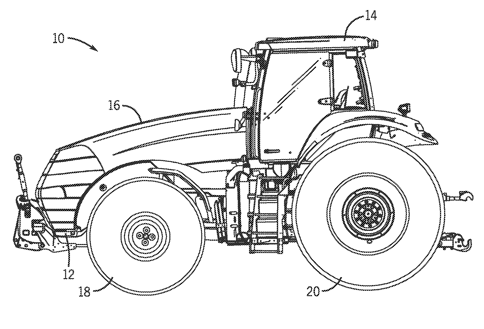
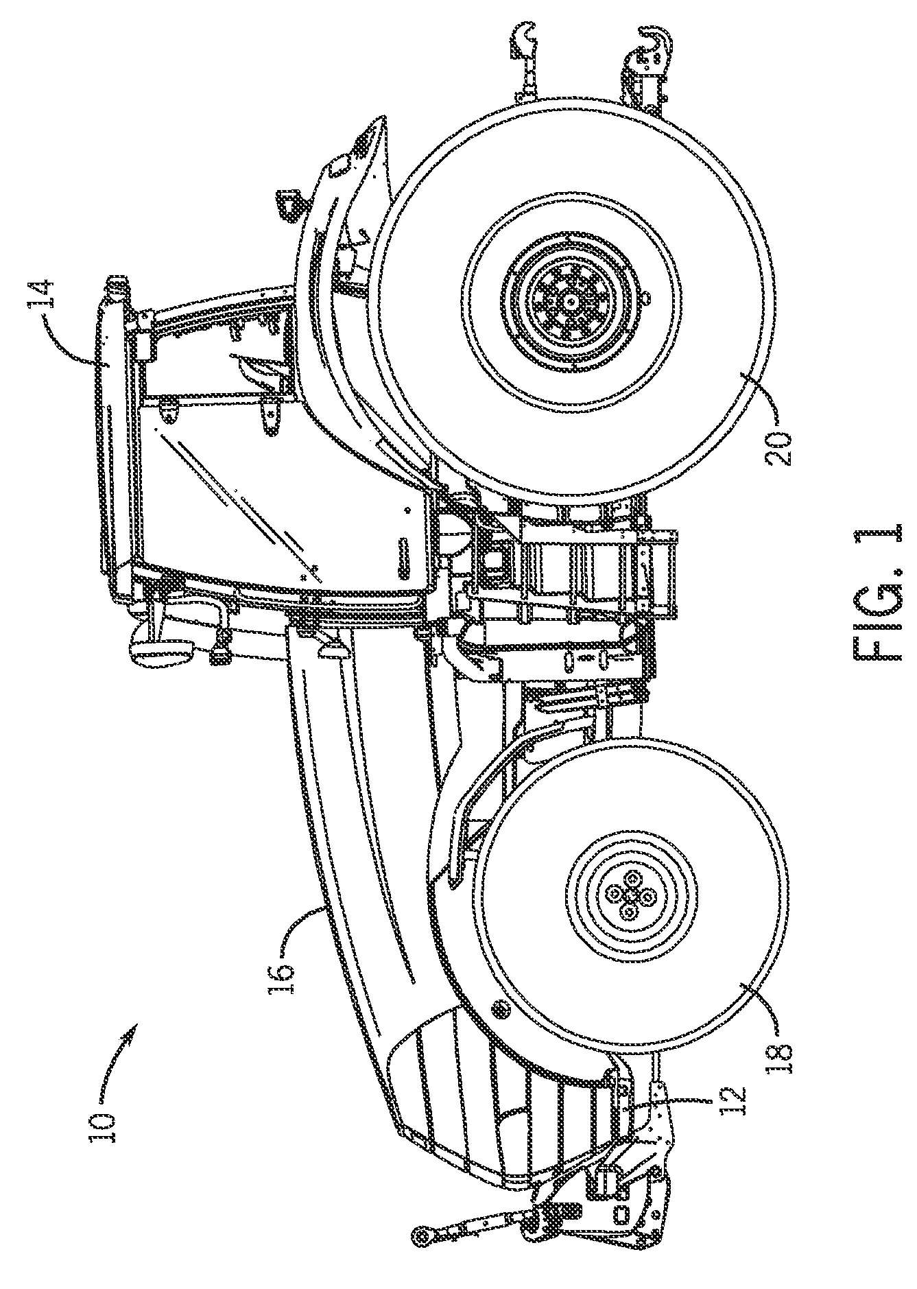
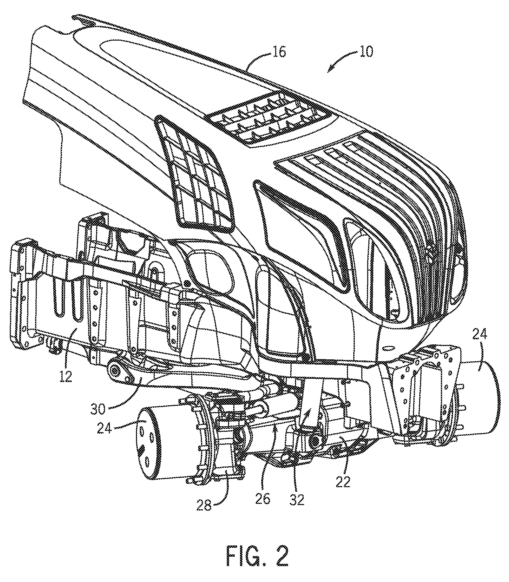
[0017]FIG. 1 is a side view of an exemplary work vehicle 10 that may include a suspension system configured to adjust frame position based on steering angle. As illustrated, the work vehicle 10 includes a frame 12 configured to support a cab 14, a hood 16, front wheels 18, rear wheels 20, and various other components of the work vehicle 10. The cab 14 provides an enclosed space for an operator, and the hood 16 houses the engine and / or other systems configured to facilitate operation of the work vehicle 10 (e.g., hydraulic systems, pneumatic systems, electrical systems, mechanical systems, etc.). The wheels 18 and 20 are driven to rotate by the engine, thereby facilitating movement of the vehicle across a field, for example.

[0018]As discussed in detail below, the front wheels 18 are coupled to a suspension system configured to adjust a position of the frame 12 relative to a front axle based on a steering angle of the front wheels 18. For example, in certain embodiments, the suspensio...


PUM


Abstract

A suspension system is provided that includes an axle configured to support a first wheel on a first lateral end of the axle, and a second wheel on a second lateral end of the axle. The suspension system also includes a steering assembly configured to rotate each wheel relative to the axle about a substantially vertical axis. In addition, the suspension system includes an actuating cylinder extending between the axle and a frame of a work vehicle. The actuating cylinder is configured to transition the frame between a lowered position that enables the steering assembly to rotate each wheel through a first range of motion without contact between the wheels and a component of the work vehicle, and a raised position that enables the steering assembly to rotate the wheels through a second range of motion, greater than the first range of motion.

Description

CROSS REFERENCE TO RELATED APPLICATIONS[0001]This application claims priority from and the benefit of U.S. Provisional Patent Application No. 61 / 513,958, entitled “Adjustable Suspension System for a Work Vehicle,” filed Aug. 1, 2011, which is hereby incorporated by reference in its entirety.BACKGROUND[0002]The invention relates generally to work vehicles, such as tractors, and more particularly to an adjustable suspension system for a work vehicle.[0003]Work vehicles, such as agricultural tractors, may be employed to tow a variety of equipment (e.g., planters, seeders, tillage implements, etc.) through a field. Certain work vehicles include a suspension system to damp vibrations caused by uneven field conditions, thereby enhancing ride quality and reducing wear on certain work vehicle components. For example, the suspension system may include an axle configured to support a wheel on each lateral end of the axle, and an axle carrier extending between a frame of the work vehicle and t...

Claims


Application Information

Patent Timeline
Patent Type & Authority Patents(United States)
IPC IPC(8): B60G17/00
CPCB62D9/00B60G9/02B60G2300/082B60G2200/322
Inventor PFIFFNER, KENNETH CHARLESMCCASH, BENJAMIN LEERACH, DAVID
Owner BLUE LEAF I P INC
Why Eureka
Try Eureka