Cannula for dispensing fluid products, particularly for vaginal and rectal applications

a technology for vaginal and rectal applications, which is applied in the direction of rigid containers, transportation and packaging, packaging, etc., can solve the problems of affecting production costs and times, affecting the quality of products, and high production costs and production cycles, so as to facilitate the removal of longitudinal sections, reduce the dimension, and increase the flexibility

Inactive Publication Date: 2013-08-27
LAMEPLAST
View PDF6 Cites 8 Cited by
  • Summary
  • Abstract
  • Description
  • Claims
  • Application Information

AI Technical Summary

Benefits of technology

[0028]The main aim of the present invention is to provide a cannula for dispensing fluid products, particularly for vaginal and rectal applications, which is structurally and constructively very simple, that reduces production time and costs, and limits the waste of materials.
[0029]A further object of the present invention is to provide a cannula for dispensing fluid products, particularly for vaginal and rectal applications, which is of compact dimensions, is easy to handle, and which can be immediately used by users.
[0030]Another object of the present invention is to provide a cannula for dispensing fluid products, particularly for vaginal and rectal applications, which overcomes the mentioned drawbacks of the known art in an easy, effective, and low cost manner.
[0033]Spaced fold lines also extend longitudinally along the cover cap. Several of the sections remaining in the cover cap may be folded over, or bent, about the fold lines. The transverse dimensions of the cover cap is reduced so that the cover cap may be inserted into an opening in an extremity of the cannula, to serve as a push rod for the piston to slide same within the cannula to discharge the fluid product contained therein. Gripping fins are formed at the lower end of the longitudinal sections to facilitate removal of the longitudinal sections.
[0034]The removal of the section defined by the weakened, or score, lines leaves an opening in the body of the cover cap, and increases its flexibility. The cover cap may be squeezed by the user to reduce its dimension to the desired extent, or the cover cap may be deformed inwardly to fit within the opening in the cannula as it is forced therein with gentle pressure exerted by the user.

Problems solved by technology

To illustrate they are rather complex in terms of structure and assembly and that, being for hygienic reasons of the single-use type and requiring a push rod for each cylinder, they produce a considerable waste of materials.
Nevertheless, these cannulas are not without drawbacks as well, tied above all, to the need to use one or more tubes of product to load the cylinders before use.
The pre-filled cannulas are not without drawbacks however, for they are of a rather complex construction, and they have rather high production costs and production cycles.
This involves the design and building of various molds and laborious assembly operations which negatively affect the production costs and times of the cannulas, as well as producing considerable and costly material waste.
For example the fabrication of the piston in a single body piece with the cylinder is considerably complicated and hard to achieve in practice.
It should also be considered that big difficulties of a practical-manufacturing nature are encountered because of the use of the tear-off film.
The push rod involves the manufacture and the assembly of a plurality of telescopic elements, with consequent increase in time and costs of designing, producing and assembly, as well as the waste of a considerable quantity of materials.

Method used


Image

  • Cannula for dispensing fluid products, particularly for vaginal and rectal applications
  • Cannula for dispensing fluid products, particularly for vaginal and rectal applications
  • Cannula for dispensing fluid products, particularly for vaginal and rectal applications

Examples


Embodiment Construction

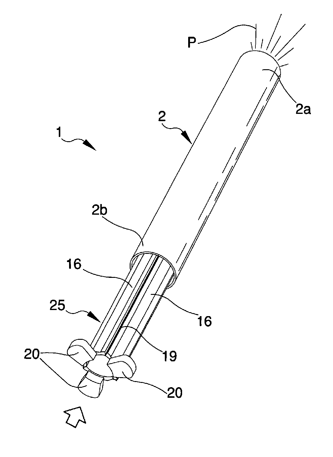
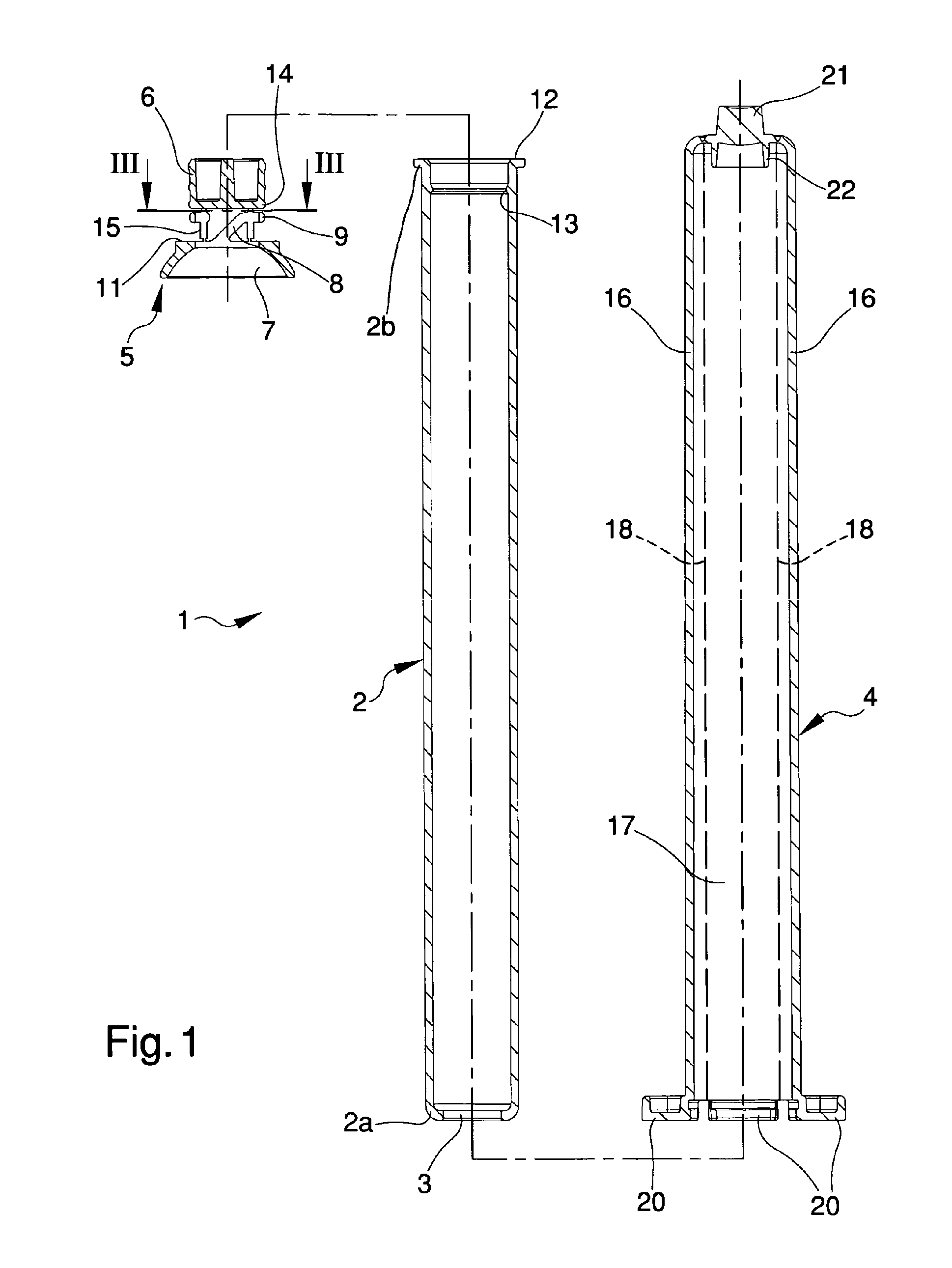
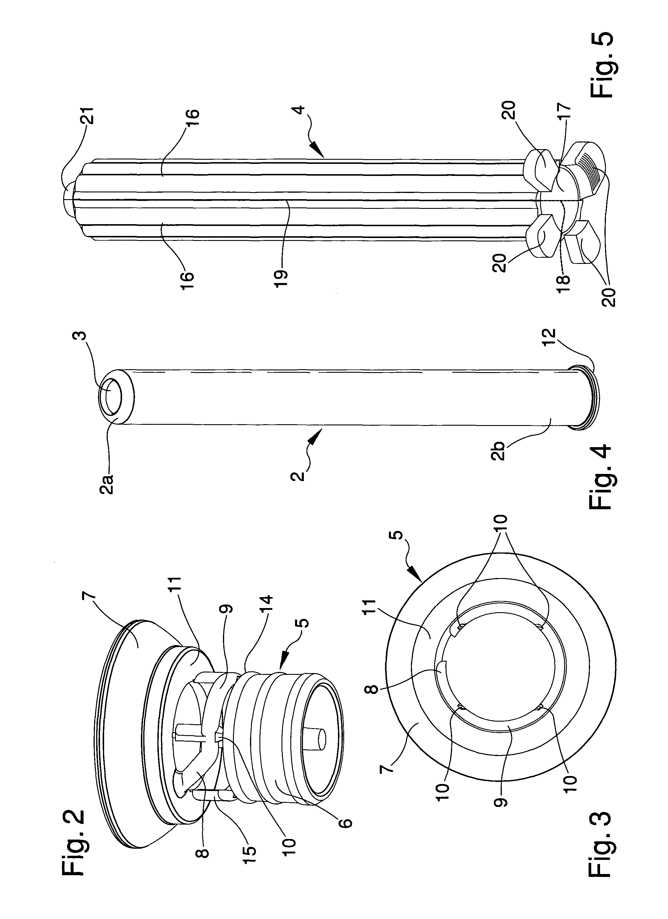
[0044]With particular reference to the embodiment of FIGS. 1 to 9, depict a cannula for dispensing fluid products, particularly for vaginal and rectal applications; the cannula is configured in accordance with the principles of applicant's invention.

[0045]In this application the term fluid products include not only liquid products but also viscous products, in the form of paste and gel, and powdered products, in particular very fine powders distinguished by great flowability.

[0046]Cannula 1 comprises a tubular body 2 which contains the fluid product P.

[0047]The tubular body 2 is shaped like a straight cylinder and has a first extremity 2a at which a dispenser opening 3 is formed.

[0048]In the embodiment of the figures from 1 to 9 there is only one dispenser opening 3 which extends crossways to the longitudinal direction of the tubular body 2.

[0049]Alternative embodiments of the invention are, however, possible, in which several dispenser openings 3 are provided and / or in which these ...


PUM

PropertyMeasurementUnit
lengthaaaaaaaaaa
structureaaaaaaaaaa
timeaaaaaaaaaa

Abstract

A cannula (1) for dispensing fluid products, particularly for vaginal and rectal applications, comprises: a tubular body (2) for containing a fluid product (P), having a first extremity (2a), at which a dispenser opening (3) is formed, and a second open extremity (2b), opposed to the first extremity (2a). A closing body (5) which is associable with the tubular body (2) to close the second extremity (2b). The closing body comprises a first element (6) at least partially insertable through the second extremity (2b) and suitable for acting as a sliding piston inside the tubular body (2), and a second annular body, that functions a tamper indication seal. A cover cap (4) which can be fitted on the tubular body (2) to close the dispenser opening (3) and which is made in a single body piece. Longitudinal score lines divide the cover cap into a plurality of first sections and a single second section. Fold lines extend longitudinally along the first sections. Single second section is torn away from the body along the weakened score lines, and the first sections are bent over the fold lines to form a push rod of reduced transverse dimensions. Push rod is insertable into tubular body to slide first section of closing cap along interior of cannula to discharge fluid product.

Description

CROSS-REFERENCE TO RELATED APPLICATIONS[0001]This application claims the benefit of PCT International Patent Application No. PCT / IB2010 / 000217, filed Feb. 4, 2010, and Italian Patent Application No. MO2009A000031, filed Feb. 9, 2009, in the Italian Intellectual Property Office, the disclosures of which are incorporated herein by reference.BACKGROUND OF THE INVENTION[0002]1. Field of the Invention[0003]The present invention relates to a cannula for dispensing fluid products, particularly for vaginal and rectal applications.[0004]2. Description of the Related Art[0005]Cannulas are known for dispensing medical fluid products which are used, in particular, for vaginal and rectal applications and which are generally sold in packs together with tubes or bottles containing the fluid products.[0006]The known cannulas are composed of a cylinder suitable for containing the product and inside which is a piston integral with the extremity of a push rod.[0007]The cylinder has an open extremity t...

Claims


Application Information

Patent Timeline
Patent Type & Authority Patents(United States)
IPC IPC(8): A61M5/32
CPCA61M31/00A61M3/0262
Inventor FONTANA, ANTONIO
Owner LAMEPLAST
Why Eureka
Try Eureka