Apparatus and method for generating a metering voltage output for a voltage regulator using a microprocessor

a microprocessor and voltage regulator technology, applied in the direction of automatic control, process and machine control, instruments, etc., can solve the problems of non-standard turns ratio of tertiary winding, voltage is not easily interpreted by a service technician, and digital value is not supplied to external test terminals

Active Publication Date: 2013-08-27
SIEMENS ENERGY INC
View PDF18 Cites 12 Cited by
  • Summary
  • Abstract
  • Description
  • Claims
  • Application Information

AI Technical Summary

Problems solved by technology

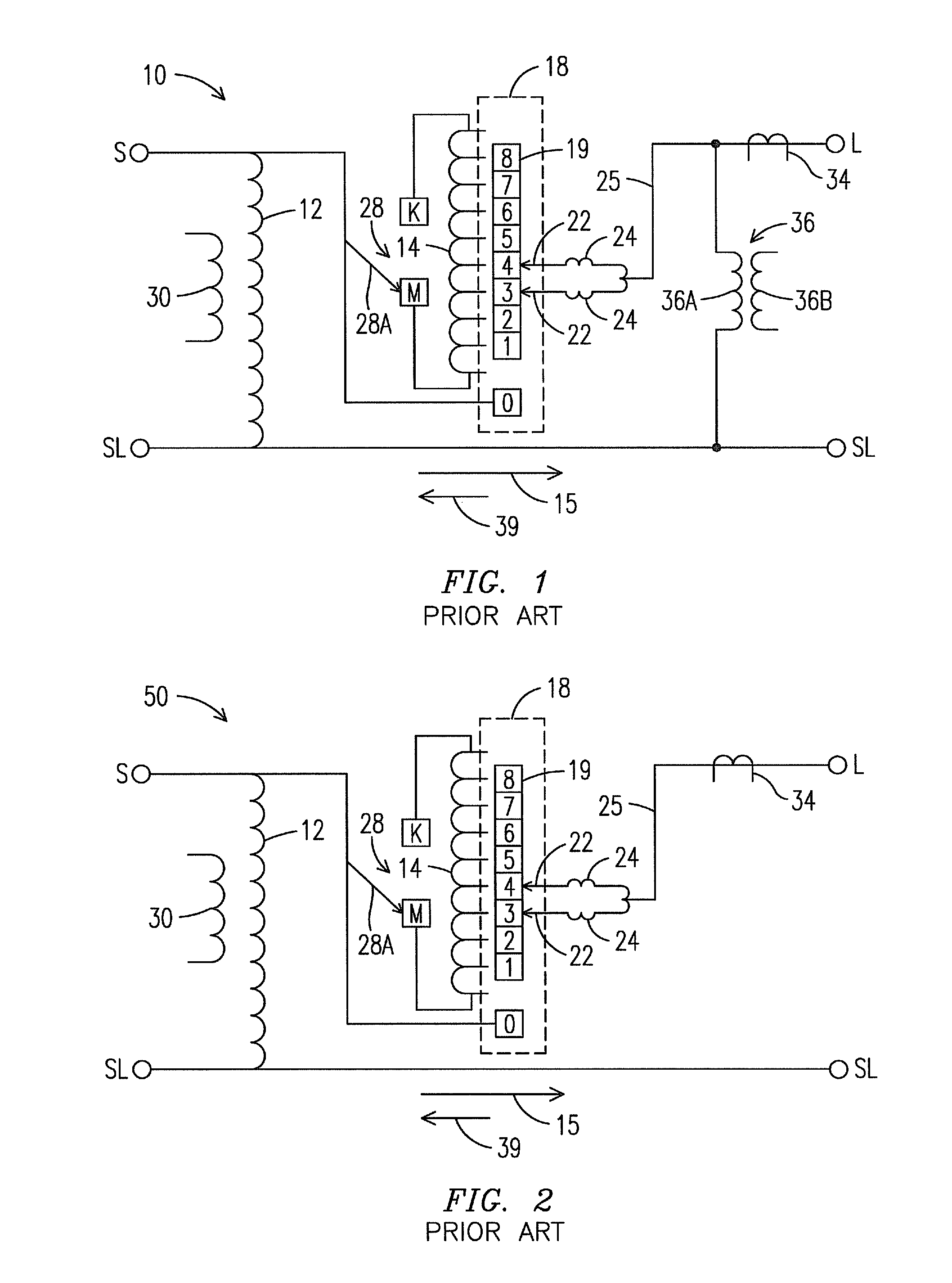
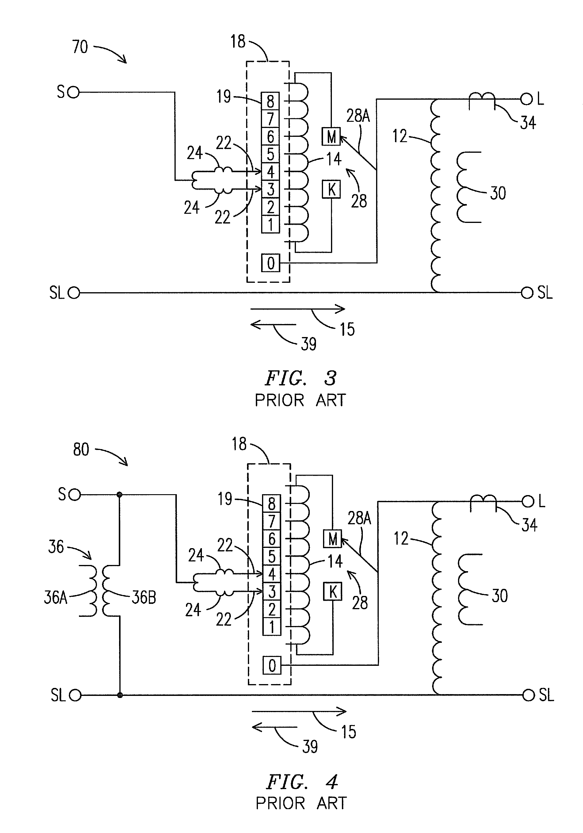
With the increasing complexity of power system interconnects and the use of automatic power restoration devices, current (power) may flow in a forward or a reverse direction through an electrical power distribution system.
Although tertiary windings have an accurate turns ratio, they typically do not have a standard or conventional turns ratios, such as 7200:120.
Although these non-standard voltages could be made available at external test terminals, these voltages are not easily interpreted by a service technician accustomed to working with transformers that produce “standard” voltages generated by transformers with a “standard” winding ratio, such as potential transformers.
However, the digital value is not supplied to external test terminals for use by service technicians in measuring a voltage regulator source voltage or load voltage.
This alternative technique for correcting the non-standard turns ratio of the tertiary winding poses a disadvantage by eliminating the ratio correction transformer.
If the service technician performing the measurement does not consider this, he will misinterpret the voltage measured at the test terminals and can inadvertently manually raise or lower the voltage beyond prescribed limits.

Method used


Image

  • Apparatus and method for generating a metering voltage output for a voltage regulator using a microprocessor
  • Apparatus and method for generating a metering voltage output for a voltage regulator using a microprocessor
  • Apparatus and method for generating a metering voltage output for a voltage regulator using a microprocessor

Examples


Embodiment Construction

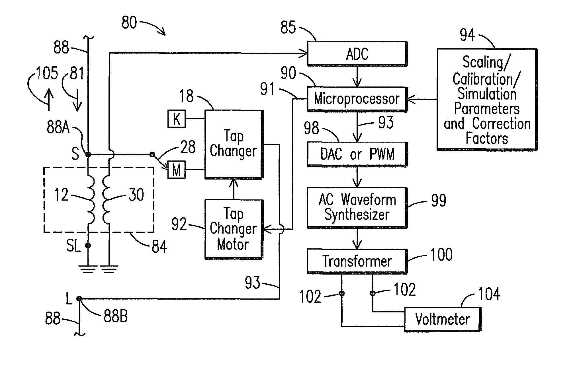
[0049]Before describing in detail the particular apparatus and method for generating a metering voltage output from a voltage regulator using a microprocessor in accordance with various aspects of the present invention, it should be observed that the present invention, in its various embodiments, resides primarily in a novel and non-obvious combination of hardware and method steps related to this apparatus and method. Accordingly, the hardware elements and method steps have been represented by conventional elements in the drawings, showing only those specific details that are pertinent to the present invention so as not to obscure the disclosure with structural details that will be readily apparent to those skilled in the art having the benefit of the description herein.

[0050]The following embodiments are not intended to define limits of the structures or methods of the invention, but only to provide exemplary constructions. The embodiments are permissive rather than mandatory and i...


PUM


Abstract

A voltage regulator (10) for regulating a power distribution system voltage during forward or reverse power flow. The voltage regulator (10) accommodates multiple configurations of a tertiary winding (30) and a potential transformer (36) connected across source-side bushings (S / SL) or load-side bushings (L / SL). The invention simulates operation of a potential transformer (36), and the output voltage therefrom, connected across the source-side (S / SL) or load-side bushings (L / SL). The invention also produces a corrected voltage compensating a non-standard turns ratio of the tertiary winding (30). The regulator (10) controls a tap changer (18) to regulate the system voltage according to a digital value representing the voltage across the source-side (S / SL) or load-side bushings (L / SL), comprising a measured voltage, the corrected voltage or the simulated voltage. The digital value is converted to an analog voltage and supplied to external terminals (102) for measuring by a service technician using a voltmeter (104).

Description

FIELD OF THE INVENTION[0001]The present invention relates to voltage regulators and, more particularly, to the use of a microprocessor to simulate an output voltage, nominally an output voltage that is based on a common distribution transformer ratio and available for measuring at external test terminals.BACKGROUND OF THE INVENTION[0002]A voltage regulator is a power quality device that provides a stable output voltage despite fluctuations in an input voltage. Voltage regulators are typically located at distribution substations and on single power line feeders. For example, if an input voltage fluctuates between 110 VAC and 130 VAC, the voltage regulator maintains the output voltage at a constant 120 VAC. The voltage regulator operates by comparing the actual output voltage (which is either measured directly or calculated as described below) to a fixed reference voltage set point (a user-defined setting). The reference voltage setpoint is typically stored within a regulator control ...

Claims


Application Information

Patent Timeline
Patent Type & Authority Patents(United States)
IPC IPC(8): G05F1/153
CPCG05F1/14
Inventor MATHEWSON, JOEL C.
Owner SIEMENS ENERGY INC
Why Eureka
Try Eureka