Wiring connection apparatus

a technology of wiring connection and wiring cable, which is applied in the field of wiring connection apparatus, can solve the problems of difficult to fit the optical adaptor b>3, high density, and difficult expansion, and achieve the effects of convenient optical cable routing and ease of use, simple expansion, and safe rou

Active Publication Date: 2013-09-03
FUJITSU LTD
View PDF13 Cites 0 Cited by
  • Summary
  • Abstract
  • Description
  • Claims
  • Application Information

AI Technical Summary

Benefits of technology

[0017]In view of the above described problems, it is the object of the present invention to provide a wiring connection apparatus, which allows dense installation (i.e. installation of a large number) of the optical adaptors for connecting the optical cables, a small apparatus size (i.e. a thin construction), and simple expansion, and realizes favorable optical cable routing and ease of use. Further, it is the object of the present invention to provide a wiring connection apparatus, which allows the optical cables to be routed safely without risk of damage.

Problems solved by technology

However, in the conventional patch panel 10 shown in FIG. 1, it is difficult to fit the optical adaptors 3 at high density (in large numbers) for connecting the optical cables 7 and 8.
Moreover, since the conventional patch panel 10 shown in FIG. 1 is constructed with the optical adaptors 3 fitted in the plate-form panel 2, the patch panel 10 must be of a predetermined large size, making expansion difficult.
Hence, in operations such as that of pulling cables connected from the rear side of the panel 2 (the optical cables 8 in the example shown in FIG. 1) to the front side of the panel 2, there is a risk of damage caused by unanticipated loads caused by the operator snagging the cables or the like.

Method used


Image

  • Wiring connection apparatus
  • Wiring connection apparatus
  • Wiring connection apparatus

Examples


Embodiment Construction

[Description of the Preferred Embodiments]

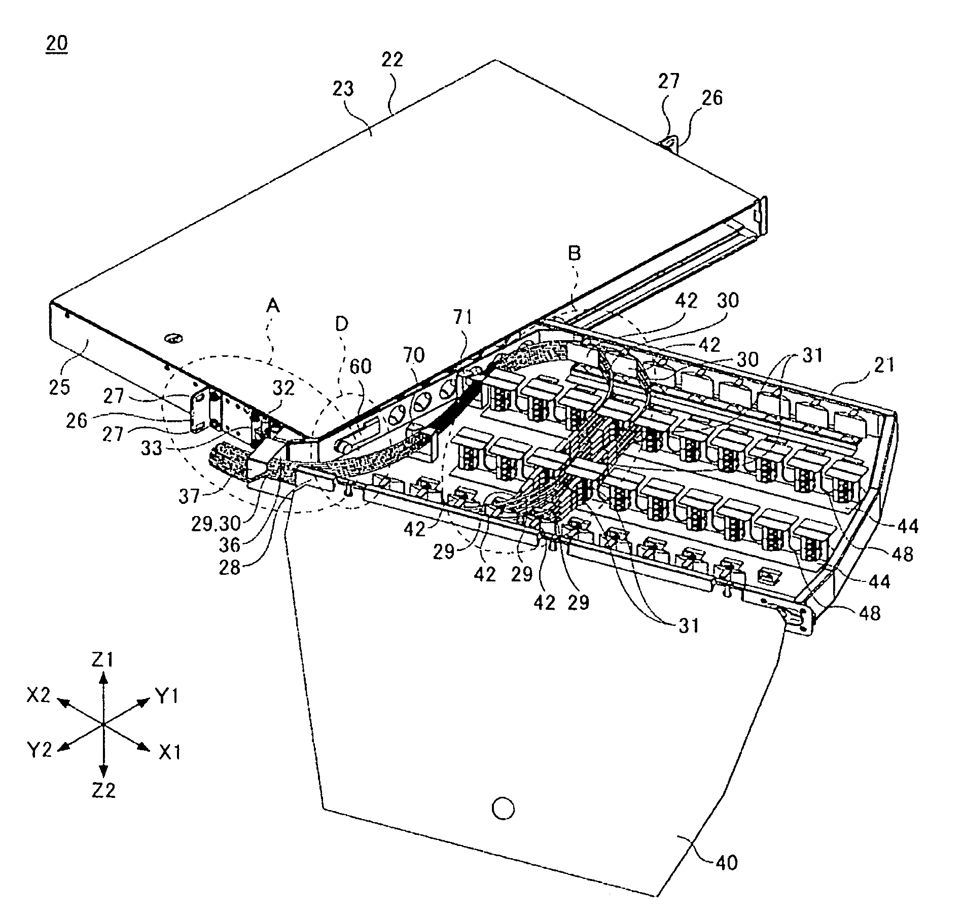
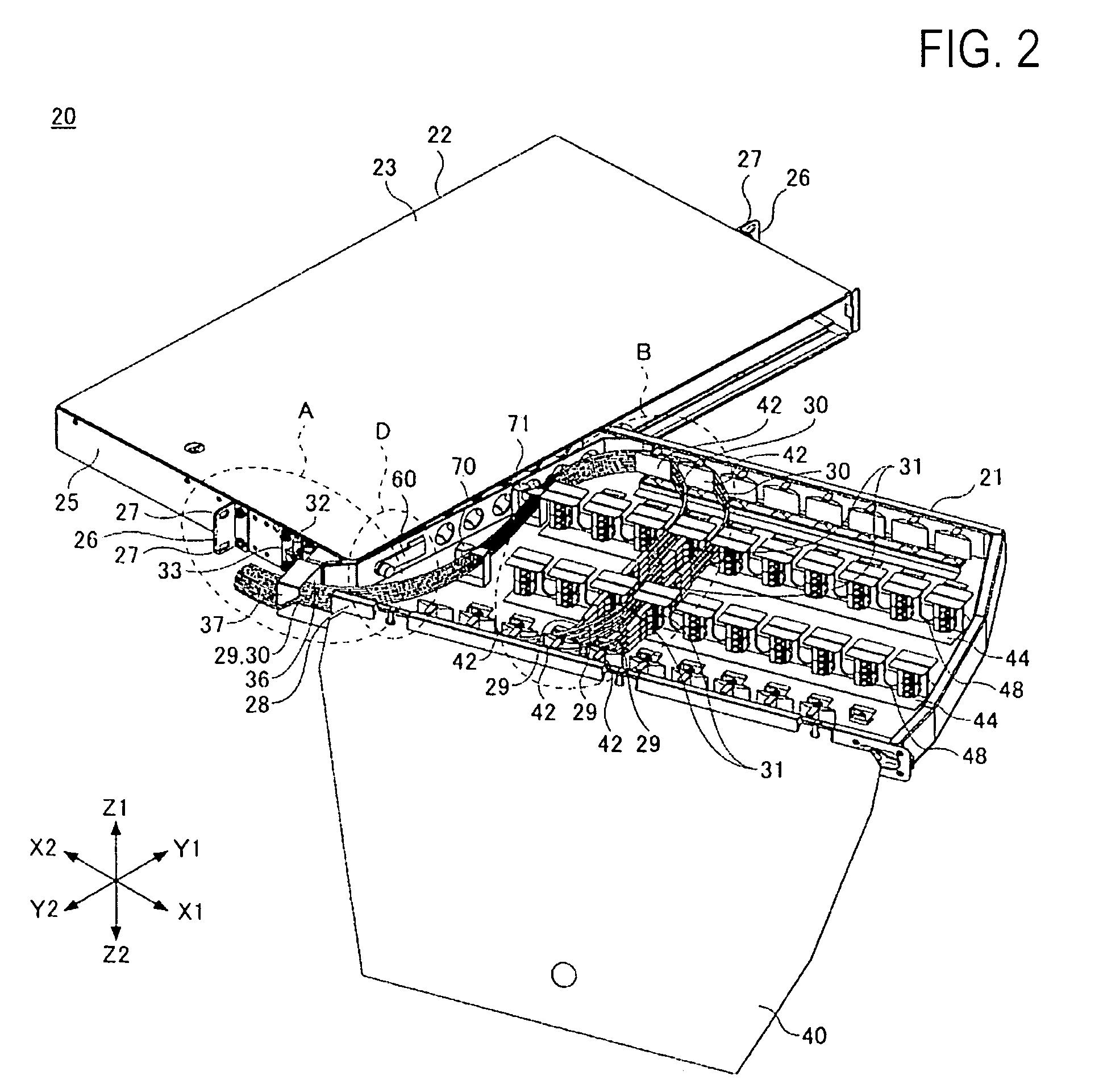
[0037]The following describes an embodiment of the present invention with reference to the drawings. FIG. 2 is a perspective view of an overall construction of a patch panel 20 according to the embodiment of the present invention.

[0038]FIG. 2 shows a state in which a tray 21 is rotated with respect to a tray holder body 22 and a transparent sheet 40 for covering the tray 21 is open.

[0039]As an example of the wiring connection apparatus of the present invention, the patch panel 20 has a depth direction (X1-X2 direction in FIG. 2) length of approximately 30.5 cm (12 inches), a width (Y1-Y2 direction length) of approximately 58.3 cm (23 inches), and a height of 1 U (4.445 cm). The height of a metal rack in which the patch panels are fixed is generally expressed in units of U. The patch panel 20 with the height of 1 U in the present example can therefore be used in any rack and allows simple expansion. It is to be noted, however, that the above ...


PUM

PropertyMeasurementUnit
lengthaaaaaaaaaa
widthaaaaaaaaaa
widthaaaaaaaaaa

Abstract

According to an aspect of an embodiment, a wiring connection apparatus comprises a tray including a plurality of wiring connection members for connecting a plurality of wiring and a tray holder body, which holds the tray, wherein the tray is rotatably provided in the tray holder body, and a wiring introduction opening for introducing the plurality of wiring into the tray is formed in proximity to an axis of rotation of the tray.

Description

CROSS REFERENCE TO RELATED APPLICATION[0001]This application claims priority to Japanese Patent Application No. 2007-001019, filed on Jan. 9, 2007.BACKGROUND[0002]The present invention relates to a wiring connection apparatus, and particularly to a wiring connection apparatus for relay connecting wiring on a first side to wiring on a second side in electronic apparatus such as communications apparatus, information processing apparatus, and measuring apparatus.DESCRIPTION OF THE RELATED ART[0003]When connecting cables, a wiring connection apparatus including a plurality of adaptors, which allow free insertion and removal of cables, is used to simplify the change of connection relationships between the cables. This type of wiring connection apparatus is known as a patch panel, and is used to support network wiring operations.[0004]FIG. 1 is a perspective view of a construction of a conventional patch panel.[0005]As shown in FIG. 1, in a conventional patch panel 10, a frame 1 mounted o...

Claims


Application Information

Patent Timeline
Patent Type & Authority Patents(United States)
IPC IPC(8): B23P19/00H01R43/00
CPCH01R9/2416H01R9/223Y10T29/53322Y10T29/53243Y10T29/53257Y10T29/49194Y10T29/53217
Inventor HOSHINO, YOSHINORIYAMAZAKI, NAOYAKATAGIRI, HIROSHIMATSUMOTO, HIDEAKI
Owner FUJITSU LTD
Why Eureka
Try Eureka