DC power source for a high voltage power apparatus

a high-voltage power apparatus and power source technology, applied in the direction of transmission, electric power transfer ac network, power distribution line transmission, etc., can solve the problems of dc circuit breakers that cannot be used in the field of dc power sources, the rating of these breakers is considerably low, and the string which includes the failed switch will be disconnected

Inactive Publication Date: 2013-09-03
ABB RES LTD +1
View PDF6 Cites 0 Cited by
  • Summary
  • Abstract
  • Description
  • Claims
  • Application Information

AI Technical Summary

Benefits of technology

[0009]It is an object of the present invention to provide an attractive solution to the above mentioned problem.
[0017]An advantage with the dc power source according to the invention is that the resulting current path when a failed switch has been bypassed enables the dc power source to remain in operation as long as redundant switches are available. Another advantage is that the dc power source is more robust and easier to maintain. Moreover, since the solid-state switches are distributed in the string it is possible to reduce the total voltage rating of the switches by 50 percent since in case mechanical dc circuit breakers are used both the breakers must have a breaking capability that equals the entire voltage across the dc power source to be able to disconnect the dc power source from the positive and negative dc rail, respectively.
[0019]All switches in the string are arranged so that they are turned on and off simultaneously, implying that each switch only has to withstand its corresponding part of the voltage across the dc power source when the string is disconnected. This embodiment reduces the risk for causing over voltages due to some switches turning off earlier than others in the string.
[0023]In accordance with an embodiment of the invention, the dc power source members are battery cells. By using battery cells as dc power source members it is possible to charge the high voltage dc power source with energy at occasions when there is excessive power available in the high voltage electrical power system, to be used at other occasions when there is a deficit of power in the system.
[0026]In accordance with an embodiment of the invention each switch comprises a plurality of interconnected controllable semiconductors. One example of a plurality of interconnected controllable semiconductors is a plurality of controllable semiconductors connected in series. This feature makes it possible to use controllable semiconductors with current ratings that are high enough even though its voltage ratings are below the requisite. Alternatively, the plurality of interconnected controllable semiconductors is a plurality of controllable semiconductors connected in parallel. This feature makes it possible to use controllable semiconductors with voltage ratings that are high enough even though its current ratings are below the requisite.

Problems solved by technology

However, the availability of dc circuit breakers is limited and the ratings of these breakers are considerably low and less than the required voltage ratings in high voltage electrical power systems.
However, a problem with most of the commercially available solid-state switches is that they become an open-circuit when failed, which means that if the solid-state switch fails, the string which includes the failed switch will be disconnected.
As a consequence the dc power source will have its capability significantly reduced.

Method used


Image

  • DC power source for a high voltage power apparatus
  • DC power source for a high voltage power apparatus
  • DC power source for a high voltage power apparatus

Examples


Embodiment Construction

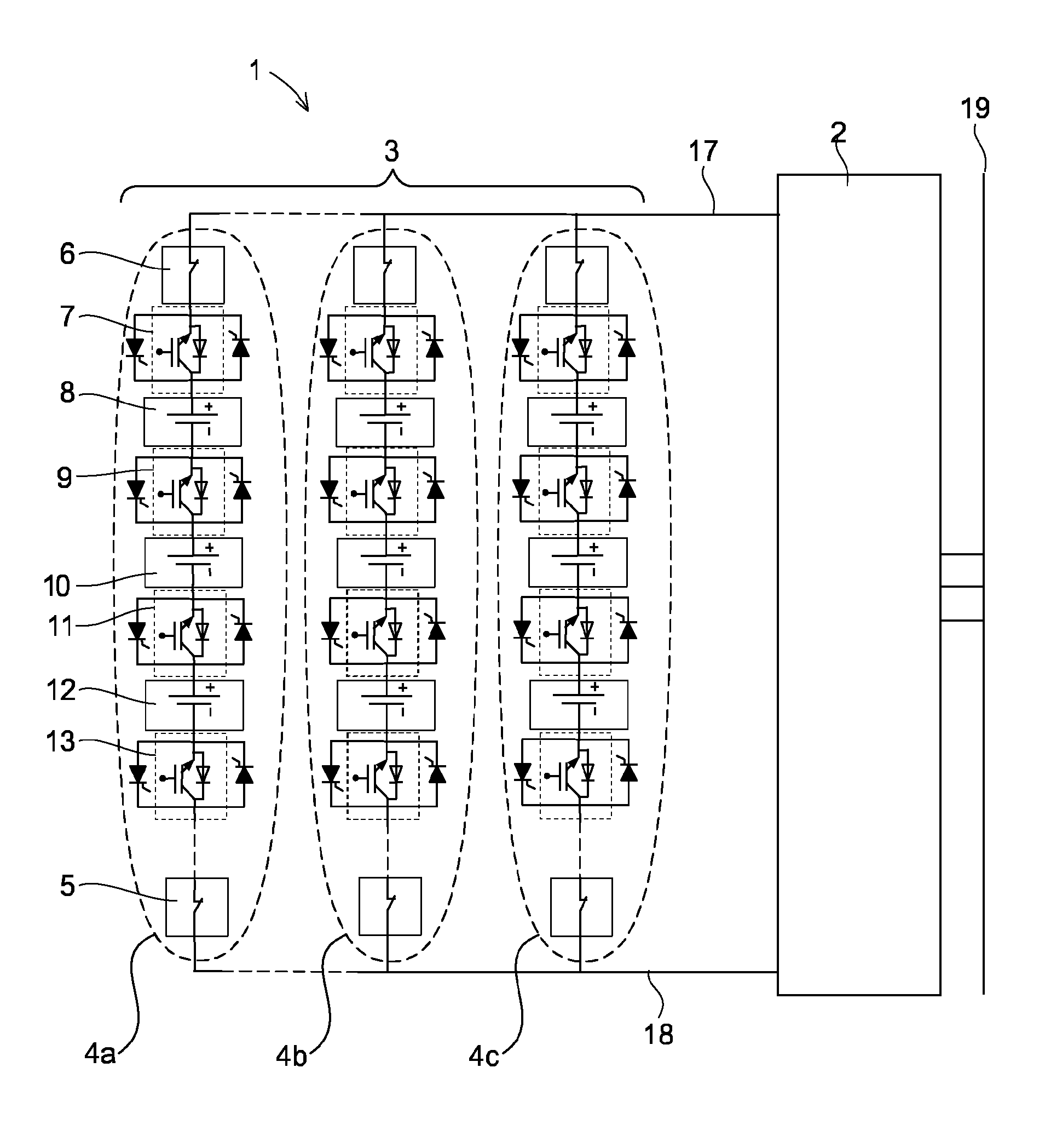
[0039]An example of a dc power source according to the invention is illustrated in FIG. 1. FIG. 1 shows a dc power source 3 for a high voltage power apparatus 1 connected to a high voltage electrical power system 19 according to an embodiment of the invention. Examples of high voltage power apparatus are a power compensator and an uninterruptible power supply (UPS). High voltage electrical power systems can be networks for transmission or distribution of electrical energy as well as industries, hospitals and such. The same reference numerals are used throughout the figures for same or corresponding parts. The power apparatus 1 comprises a high voltage dc power source 3 and a voltage source converter 2. To be able to produce and absorb not only reactive power but also active power, the dc power source 3 is connected to the dc side of the voltage source converter 2. The ac side of the converter is connected to the high voltage electrical power system 19.

[0040]The dc power source 3 com...


PUM


Abstract

A dc power source for a high voltage power apparatus, the dc power source including one or more strings including a plurality of dc power source units connected in series, and switches configured to connect and disconnect said strings. The switches are solid-state switches distributed among the power source units of each string, and all solid-state switches in the string are arranged so that they are turned on and off simultaneously. Each switch is connected in parallel with a first controllable semiconductor in a first direction and connected in parallel with a second controllable semiconductor in a second direction which is opposite to the first direction, and the dc power source includes a control unit configured to bypass a failed switch by triggering the forward biased of the first or second controllable semiconductor connected to the failed switch in case a fault in the switch is detected.

Description

CROSS-REFERENCE TO RELATED APPLICATIONS[0001]The present application is a continuation of pending International patent application PCT / EP2009 / 066865 filed on Dec. 10, 2009 which designates the United States and the content of which is incorporated herein by reference.FIELD OF THE INVENTION[0002]The present invention relates to a dc power source for a high voltage power apparatus connected to a high voltage electrical power system, the dc power source comprising one or more strings including a plurality of dc power source members connected in series, and switches configured to connect and disconnect the strings. By a high voltage electrical power system should be understood an electrical system within the range of 3 kV and upwards, preferably in the range of 10 kV and upwards. By a dc power source should be understood dc power source members connected in series to be within the range of 3 kV and upwards. With a power apparatus is meant an apparatus that is capable of controlling reac...

Claims


Application Information

Patent Timeline
Patent Type & Authority Patents(United States)
IPC IPC(8): H04B3/54H02M1/00
CPCH02J3/1835H02M1/32H02M2001/0077Y02E40/30H02M1/0077H01L29/7395H02J3/18H02J3/36H02J7/34H03K17/0822
Inventor PAPASTERGIOU, KONSTANTINOSHERMANSSON, WILLYDEMETRIADES, GEORGIOS
Owner ABB RES LTD
Why Eureka
Try Eureka