Downhole hydraulic ram

a hydraulic ram and downhole technology, applied in machines/engines, borehole/well accessories, sealing/packing, etc., can solve the problems of not being able to pump salt water to the surface, the wellbore should not be completed, and the salt water is not normally useful for agrarian activities, so as to improve the water quality and improve the lower aquifer water quality

Inactive Publication Date: 2006-04-04
HARDGRAVE WILLIAM DAVID
View PDF5 Cites 6 Cited by
  • Summary
  • Abstract
  • Description
  • Claims
  • Application Information

AI Technical Summary

Benefits of technology

[0009]Where the upper aquifer is of good quality and the lower aquifer is undesirable or less desirable, the wellbore can be completed. The pump must be positioned above the lower aquifer's free water surface in the wellbore where there is minimal backpressure on the pump. Care must be taken to prevent waters from the lower aquifer entering the pressure chamber. Commingling the two aquifers will improve the lower aquifer water quality. The improved water quality could enable its use downstream.
[0012]The hydraulic ram or impulse pump is a device that employs the energy of the falling drive water to lift a lesser amount of delivery water higher than the source elevation. There are only two moving parts, thus minimizing the maintenance. For these reasons the hydraulic ram pump is an attractive solution where upper water strata or stratum have a large flow rate and a lower strata or stratum have the ability to receive the water are found to exist. As a rule, a hydraulic ram pump should be considered when there is a water source, free of sand, which can provide at least seven (7) times more water than the ram pump is to deliver to the surface. The following are the design factors to be considered for the successful operation of the ram pump:

Problems solved by technology

When undesirable water or constituents such as hydrocarbons are encountered in the upper aquifer, a wellbore should not be completed.
For example, salt water is not normally useful for agrarian activities and detrimental to crop growing; therefore, salt water would not be pumped to the surface for this operation.

Method used


Image

  • Downhole hydraulic ram
  • Downhole hydraulic ram
  • Downhole hydraulic ram

Examples


Embodiment Construction

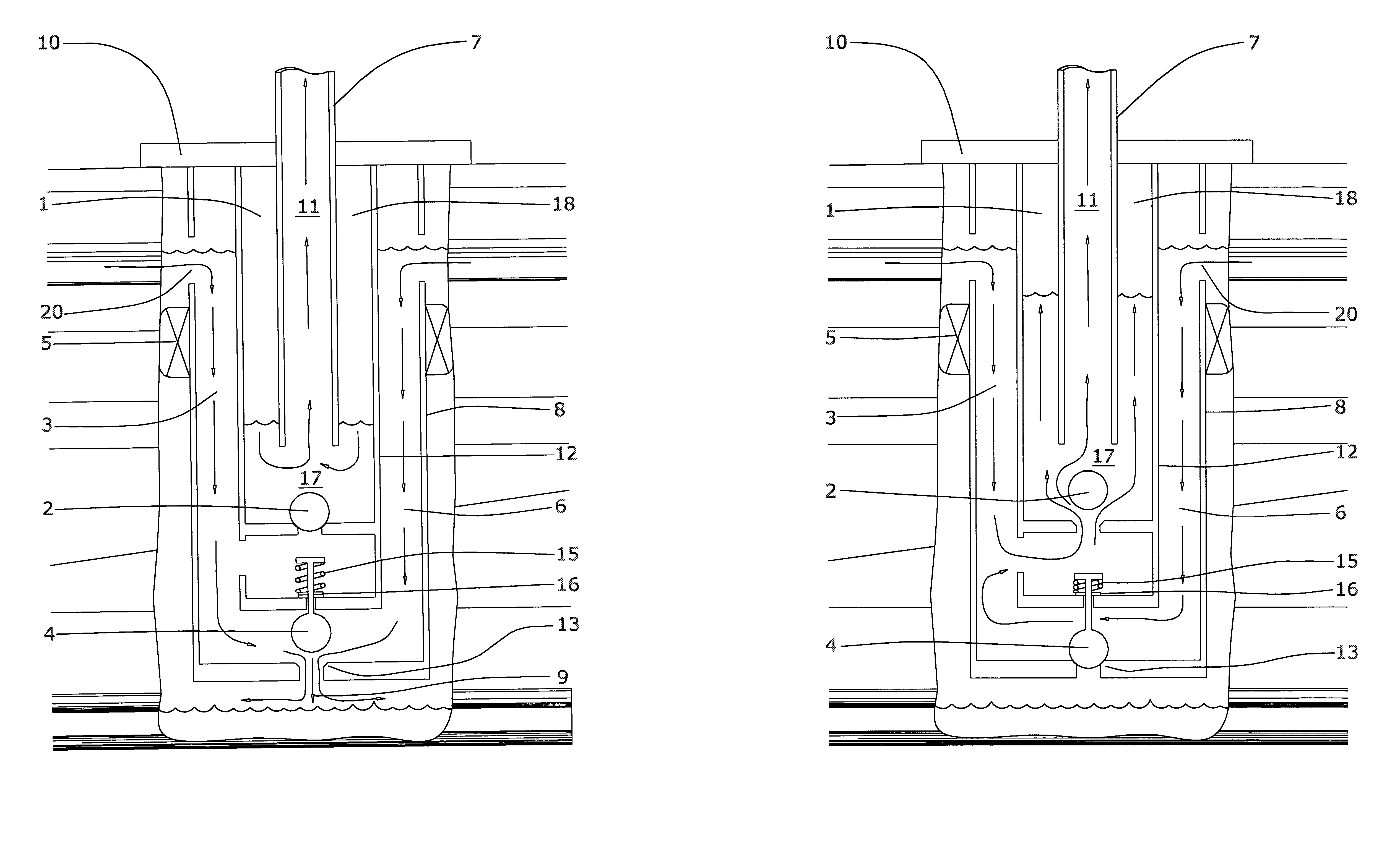
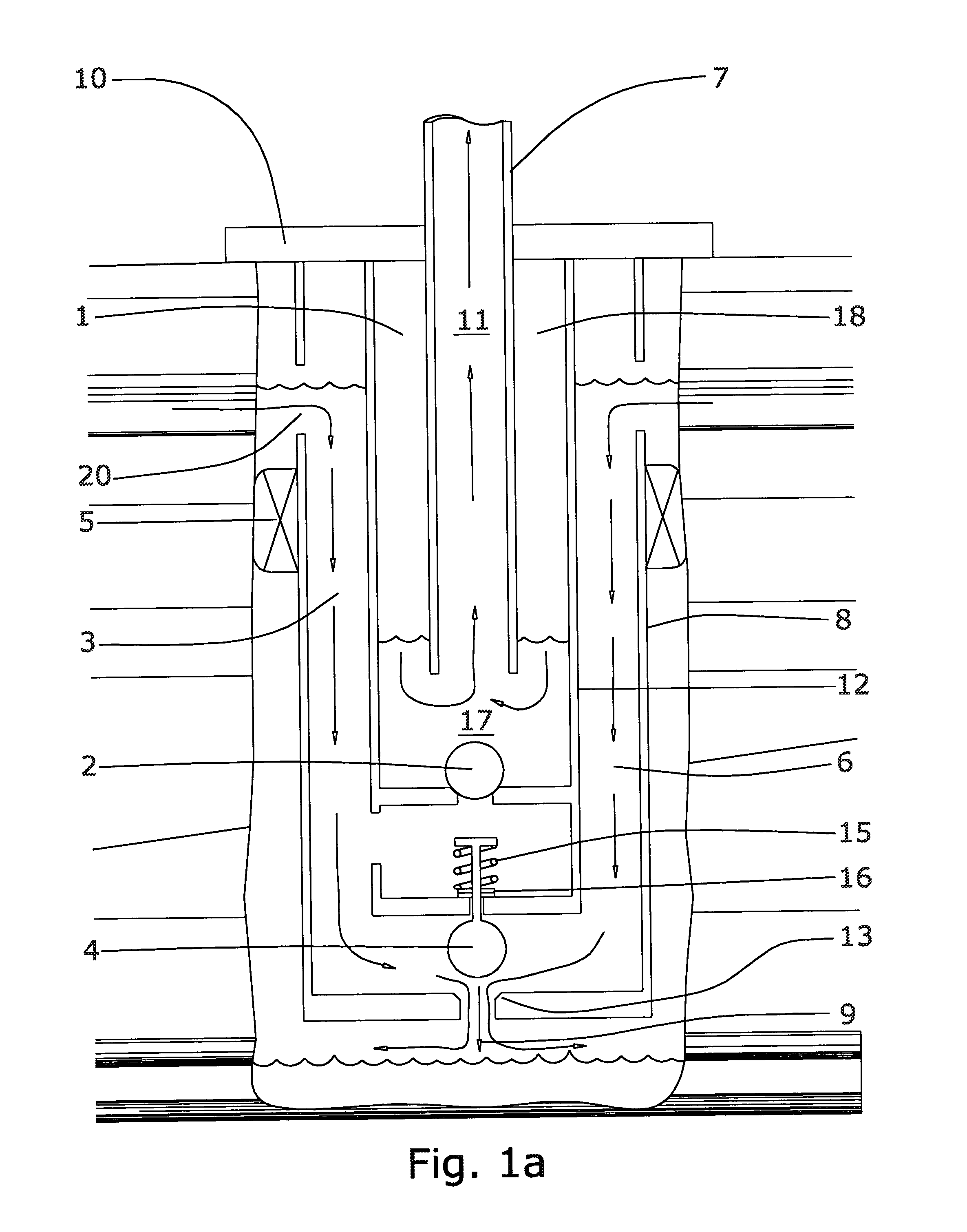
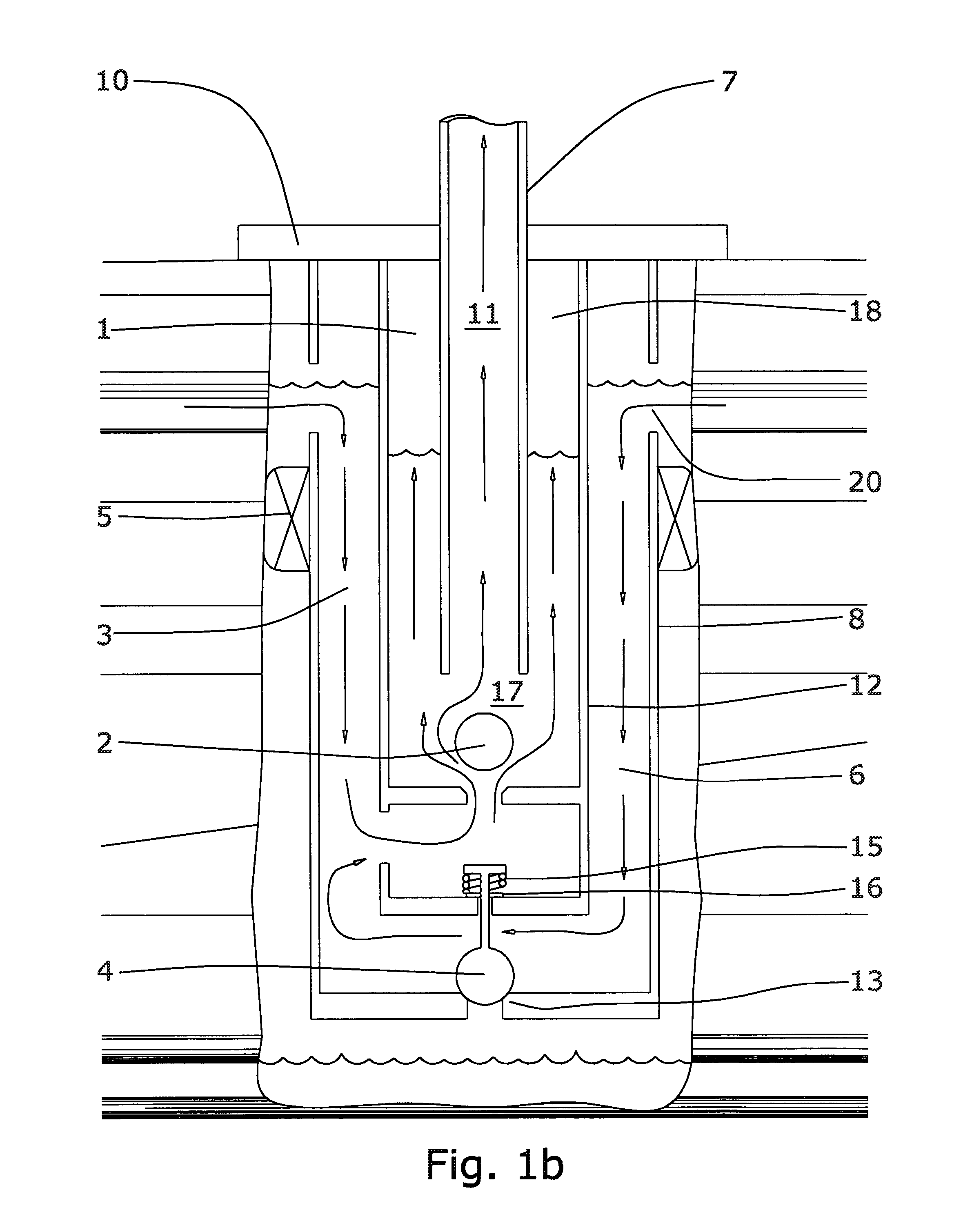
[0027]An object of this invention is to install the casing 8 (The casing discussed here is actually a large size production tubing. The wellbore liner, commonly referred to as casing, that is normally cemented in place is not discussed in this description but is in the claims.) from the surface to the desired location for the valving means. The casing 8 is provided with porting 20 located at the upper supply water level to allow the water to flow into the outer annulus 6 and fall downward to the hydraulic ram valving means. Porting 20 means to control the flow are also included in this invention. Well-known oil and gas equipment such as orifices, ported nipples, sliding side doors, and ball and flapper valves can be used. Sealing system means comprised of isolation packers 5 or cement are used to prevent the bypass of water between the earth wellbore wall and the casing 8 directing the flow to the porting means 20. A manifold for gathering water such as gravel pack and horizontal bo...


PUM


Abstract

A system and method for pumping water from a wellbore to a surface location using an improved motorless water pump. The improved motorless water pump is a downhole hydraulic ram pump powered by the renewable energy source, groundwater. As water falls down a wellbore from an upper strata to a lower strata, the conversion of the water's momentum to energy is used to compress air captured in the ram's pressure chamber. The compressed air contained in the pressure chamber pushes down on the water captured in the pressure chamber causing the water to exit the pressure chamber through an outlet and into tubing. The water in the tubing is responsive to the pressure in the chamber rising to the surface.

Description

RELATED APPLICATIONS[0001]This Application is related to, and claims the benefit of the filing dates of U.S. Provisional Patent Application No. 60 / 324,026, filed Sep. 24, 2001, and U.S. Provisional Patent Application No. 60 / 345,566, filed Jan. 7, 2002, all of which are incorporated herein by reference.TECHNICAL FIELD OF THE INVENTION[0002]It is an object of this invention to provide an improved motorless water pump. It is a further object of this invention to provide a motorless pump utilizing fluid flow and momentum thereof to lift the fluid to a higher location. It is an object of this invention to provide a motorless pump to lift water from a wellbore to a higher ground elevation for storage and use.BACKGROUND OF THE INVENTION[0003]The well-known hydraulic ram pump originated in 1772 when J. Whitehurst theoretically invented the concept. Not until 1797 was the idea filly developed and patented by J. M. de Montgolfier. The Montgolfier invention could lift water to a high altitude ...

Claims


Application Information

Patent Timeline
Patent Type & Authority Patents(United States)
IPC IPC(8): E21B43/00E21B43/12E21B43/14F04F7/02
CPCE21B43/121F04F7/02E21B43/14E03B5/04
Inventor HARDGRAVE, WILLIAM DAVID
Owner HARDGRAVE WILLIAM DAVID
Why Eureka
Try Eureka