
Control method for a printer and a printer

a control method and printer technology, applied in the direction of digital output to print units, instruments, digitally marking record carriers, etc., can solve the problems of complex processing, delay in the timing at which the buzzer should actually sound, and the structure of print command and printer-side processing becomes complicated

Active Publication Date: 2013-09-03
SEIKO EPSON CORP
View PDF22 Cites 0 Cited by
  • Summary
  • Abstract
  • Description
  • Claims
  • Application Information

AI Technical Summary

Benefits of technology

The solution enables the buzzer to sound accurately and promptly at specified times without delays, simplifying the command structure and allowing flexible configuration of buzzer triggers and sounds, improving user notification during printing operations.

Problems solved by technology

Therefore, if the setting for sounding the buzzer is complicated, such as sounding the buzzer at every n-th page end operation, the audible report configuration command must be resent each time the buzzer is sounded, and processing becomes complex.
First, because the printer interprets the buzzer commands contained in the print command to sound the buzzer each time (in the order) the buzzer is to be sounded, there is a delay to the timing at which the buzzer should actually sound.
Furthermore, because a buzzer command is required each time the buzzer sounds, the structure of the print command and printer-side processing become complicated.
Because sounding the buzzer waits until the head cleaning process ends once the head cleaning process starts, the timing at which the buzzer sounds to notify the user that printing ended is significantly delayed from the actual end of printing.

Method used


Image

  • Control method for a printer and a printer
  • Control method for a printer and a printer
  • Control method for a printer and a printer

Examples


Embodiment Construction

[0036]A preferred embodiment of the present invention is described below with reference to the accompanying figures.

[0037]General Configuration

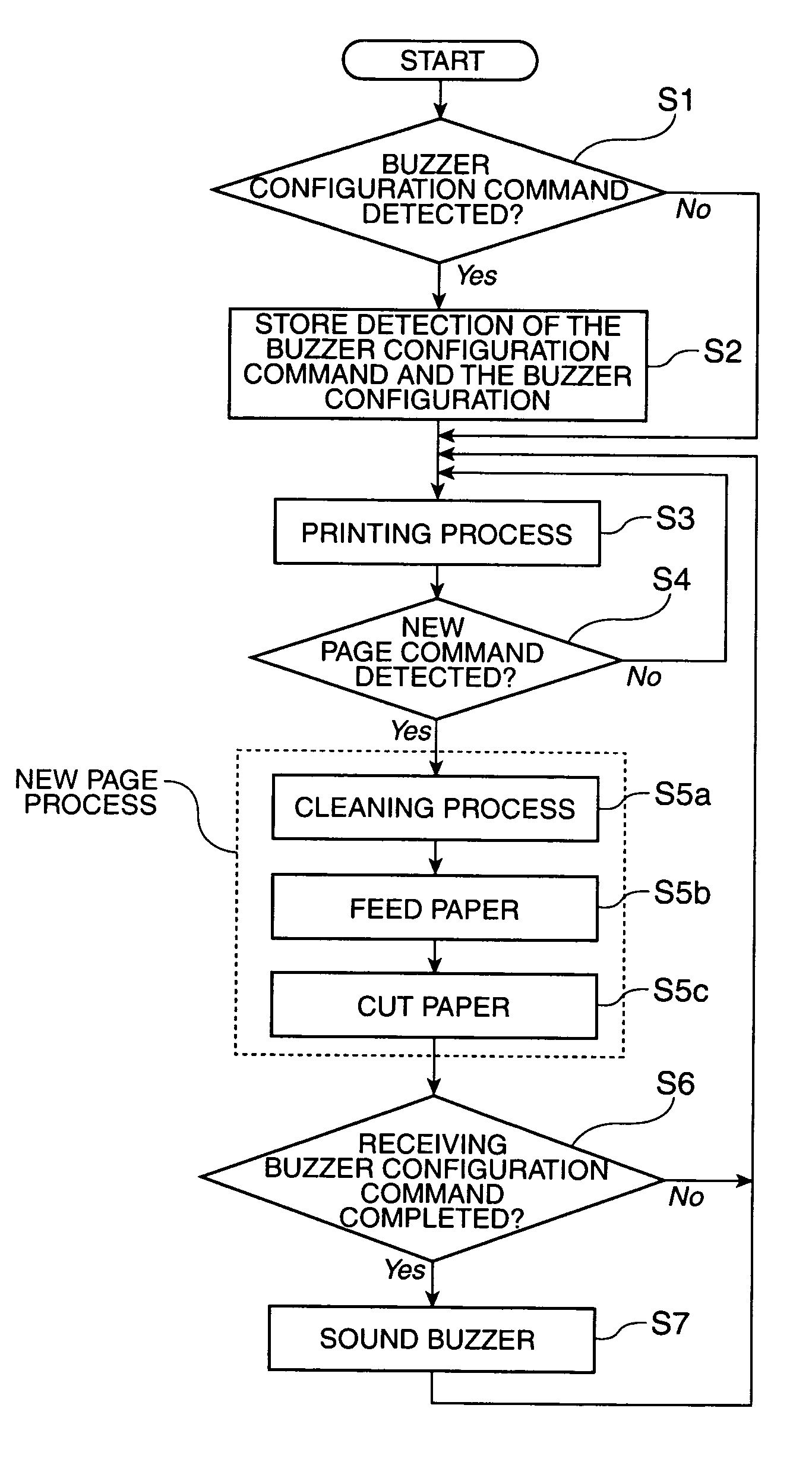
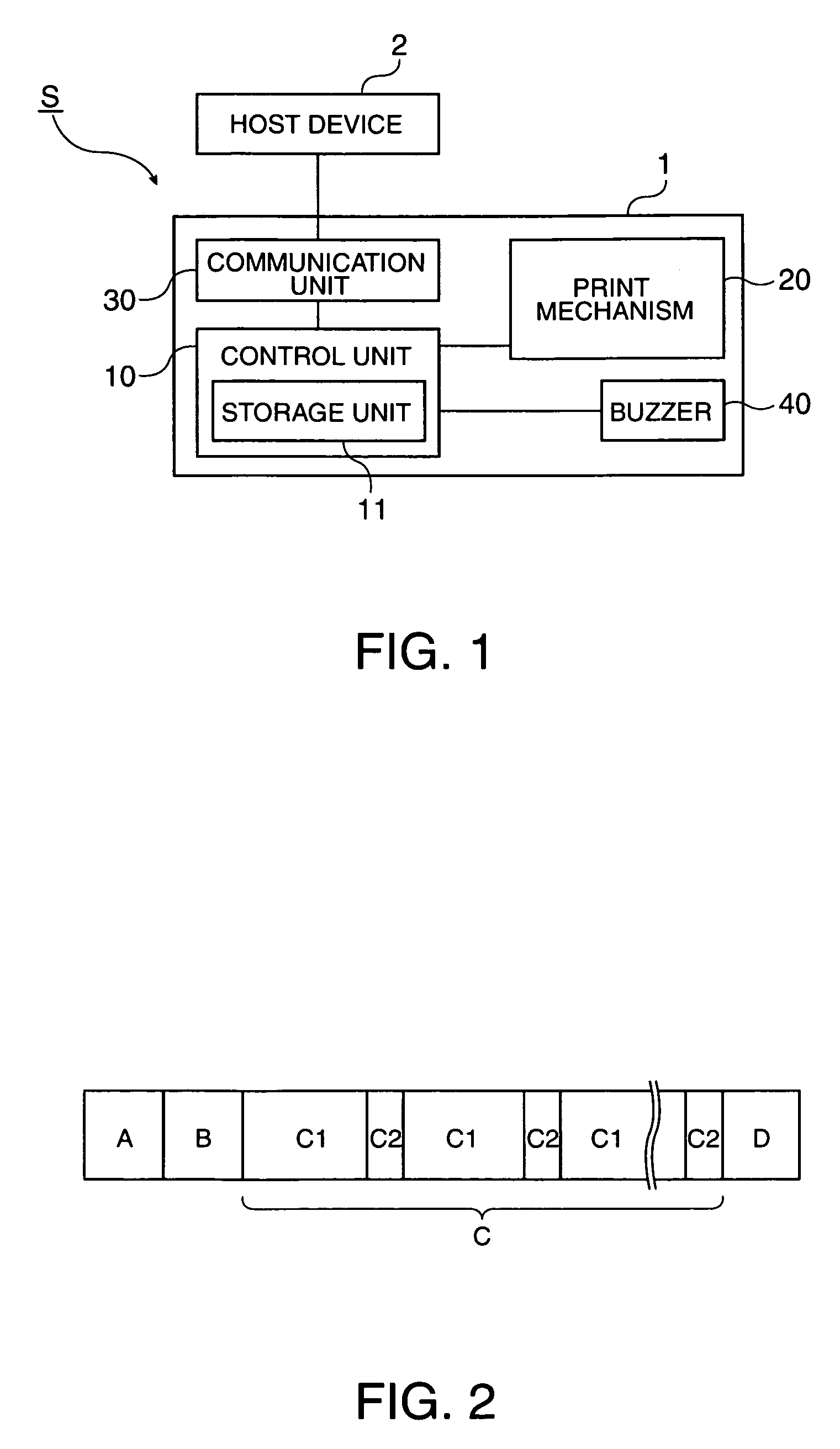
[0038]FIG. 1 is a block diagram showing the general configuration of a printer system S including a host device 2 and a buzzer-equipped inkjet printer 1 according to at least one embodiment of the present invention. As shown in FIG. 1, the printer 1 includes a control unit 10 that controls various parts of the printer, a print mechanism 20 that prints on recording paper according to control signals from the control unit 10, a communication unit 30 that is an interface for communicating with the host device 2, and a buzzer 40 that sounds according to a control signal from the control unit 10. The printer 1 also has a power supply unit and operating unit not shown.

[0039]The control unit 10 has a CPU or processing unit, and a storage unit 11. The storage unit 11 includes flash ROM or EEPROM that stores programs and data required for configuratio...


PUM


Abstract

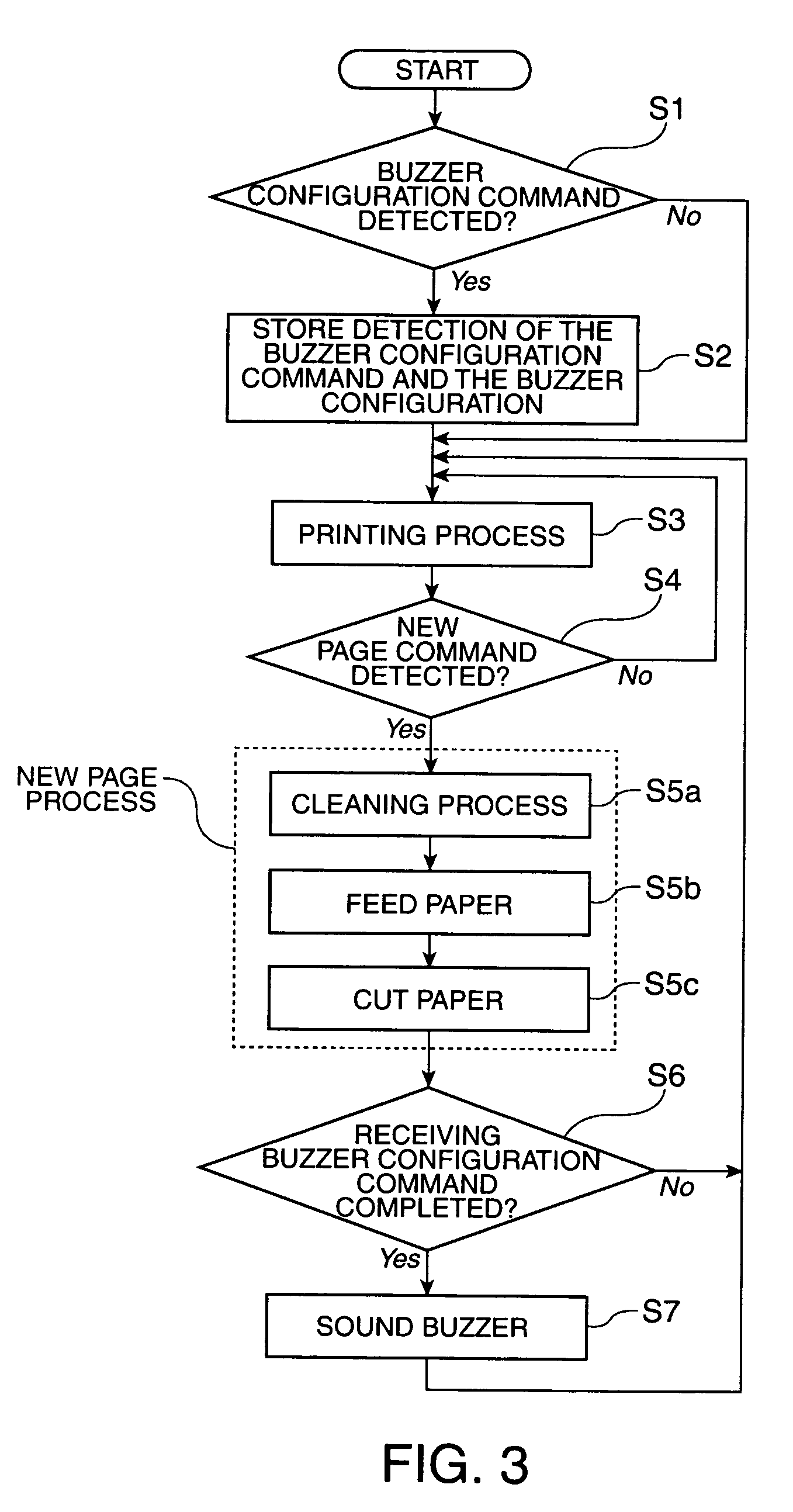
Sounding a buzzer a plurality of times can be controlled with few commands, the processor load is reduced when sounding the buzzer, and the buzzer can be sounded at the desired timing. A printer 1 having a buzzer 40 receives print data containing four types of data, a print configuration command A, a buzzer configuration command B, a printing control command C, and a stop printing command D, from a host device 2. The buzzer configuration command B is a command that sets the conditions and method of sounding the buzzer 40. The buzzer configuration command B sets the new page command C2 as the command that triggers sounding the buzzer 40 from among commands and data contained in the printing control command. When the control unit 10 of the printer 1 detects the new page command C2 while executing a print job, the control unit 10 causes the buzzer 40 to sound at the specified timing in the new page process.

Description

[0001]Control method for a printer and a printer This application claims priority under 35 U.S.C. §119 to Japanese Patent Application No. 2008-063735 filed on Mar. 13, 2008, the entire disclosure of which is expressly incorporated by reference herein.BACKGROUND OF THE INVENTION[0002]1. Field of Invention[0003]The present invention relates to a printer that is equipped with a buzzer and can sound the buzzer at a predetermined time linked to a printing-related operation that is triggered by sending commands and data from a host device, and further relates to a control method for a printer that is equipped with a buzzer.[0004]2. Description of Related Art[0005]Printers that equipped with a buzzer include printers that sound the buzzer when a command is sent from a host device, and printers that are preset to sound the buzzer according to the condition of the printer.[0006]The latter type of printer with a buzzer is taught in Japanese Unexamined Patent Appl. Pub. JP-A-2001-166904. This ...

Claims


Application Information

Patent Timeline
Patent Type & Authority Patents(United States)
IPC IPC(8): G06F3/12
CPCG06K15/00G06K15/1822G06K15/1805G06K15/005
Inventor ONO, MASAKAZUOI, TOMOYUKI
Owner SEIKO EPSON CORP
Learn More