Material mixture for producing a fireproof material, fireproof molded body and method for the manufacturing thereof

a technology of fireproof molded body and material mixture, which is applied in the direction of combustion apparatus, continuous combustion chamber, lighting and heating apparatus, etc., can solve the problems of increasing thermal stress, affecting the service life of heat shield elements, and causing cracks to extend ou

Inactive Publication Date: 2013-09-10
SIEMENS AG
View PDF22 Cites 2 Cited by
  • Summary
  • Abstract
  • Description
  • Claims
  • Application Information

AI Technical Summary

Benefits of technology

[0014]The first object of the invention is therefore to provide a material mixture for producing a refractory molded body which is particularly suitable for producing heat shield elements for gas turbines. A second object of the present invention is to provide an advantageous method for producing a refractory molded body such as, for example, a heat shield element for a gas turbine. A third object of the invention is lastly to provide an advantageous molded body for high-temperature gas reactors, e.g. a heat shield element for gas turbines.
[0018]Using the material mixture according to the invention, a thermal shock and corrosion resistant ceramic material can be produced which is particularly suitable for producing refractory molded bodies such as heat shield elements for gas turbines. The zirconium oxide in the material mixture is used to increase the corrosion resistance and, in particular, by forming microcracks in the matrix, to develop a high thermal shock resistance. Altogether, the material mixture can be used to produce refractory molded bodies, particularly heat shield elements for gas turbines, which have a longer service life than conventional refractory molded bodies. In particular, the use of spinel prevents the breakdown of the mullite and corundum, while nevertheless retaining the basic heat shielding properties. As a result of the longer service life, longer inspection intervals are possible which reduces the operating costs of a gas turbine. However, in addition to the molded products, unmolded products for the power industry, metallurgy, the automotive industry, the glass and cement industry and the chemical industry can be produced from the material mixture. The material mixture according to the invention can in particular also be processed without using a calcium-containing binder.
[0020]By using the material mixture according to the invention, the method according to the invention can produce a refractory molded body having the above mentioned advantages over conventional refractory molded bodies, in particular a longer service life and longer inspection intervals.
[0026]A refractory molded body according to the invention has the advantages already described with reference to the method for the production thereof and with reference to the material mixture over conventional refractory molded bodies, in particular a longer service life and a longer inspection interval.

Problems solved by technology

Therefore, particularly in the case of ceramic heat shield elements, even without contact between adjacent heat shield elements, stresses occur on the hot side which may result in crack initiation and thus adversely affect the service life of the heat shield elements.
A temperature gradient running parallel to the supporting structure, such as that running from the peripheral surfaces of the heat shield element to the center of the heat shield element, quickly brings about increased thermal stresses because of the rigidity of plate-like geometries in respect of deformations parallel to their largest projection surface.
If the material strength is exceeded, this tension can result in the initiation of cracks extending out from the edges of heat shield element toward central areas of the heat shield element.
The thermally induced cracks may lengthen as the result of mechanical stress loads occurring during operation of the gas turbine plant, causing the residual cross section to be reduced still further and possibly necessitating replacement of the heat shield element.
However, inserting flow barriers is not always easily possible and also increases the complexity of a heat shield.
In addition, heat shield elements are exposed to severe corrosive attack resulting in a lifetime-limiting loss of material.
The material loss occurring in the case of ceramic heat shield elements is attributable to a combination of corrosion, subsequent resintering of the surface and erosive stress caused by the high mass flow of hot gas.
With increasing numbers of gas turbine startups, this results in a weakening of the surface due to microcracking.
Consequently, surface particles are entrained by the high mass flow, resulting in erosion.
As a result, the service life of the heat shield elements is limited by corrosion, thereby necessitating premature replacement.
Add to this the fact that, in the case of heavy oil operation of a gas turbine, magnesium oxide is added as an inhibitor, which likewise results in corrosive thinning of the heat shield elements.
This also results in service life reduction and the need to replace the heat shield element prematurely.
In addition, the products can be sintered for the first time during use, thereby saving firing costs.
However, the disadvantage of such materials are the significantly poorer corrosion properties in a corrosive gas and / or fusion environment.
Moreover, metal heat shield elements are more prone to corrosion and, because of their lower temperature stability, cannot be subjected to as high temperatures as ceramic heat shield elements.

Method used


Image

  • Material mixture for producing a fireproof material, fireproof molded body and method for the manufacturing thereof

Examples


Embodiment Construction

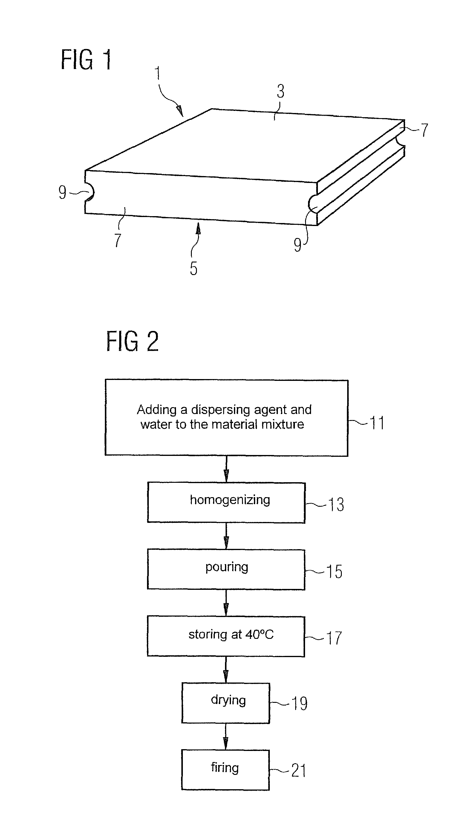
[0030]FIG. 1 schematically illustrates a heat shield element for a gas turbine combustion chamber as an example of a refractory molded body according to the invention. The heat shield element 1 shown in FIG. 1 has a hot side 3 facing the interior of the combustion chamber, a cold side 5 facing the supporting structure of the combustion chamber, and four peripheral sides 7. In two of the peripheral sides 7, grooves 9 are present which provide access to a retaining clip attaching the heat shield element 1 to the supporting structure. Self-evidently, other retention options can also be used for which the grooves 9 are unnecessary. For example, the cold side 5 of the heat shield element 1 can be bolted to the supporting structure.

[0031]The heat shield element 1 of a ceramic based on spinel and baddeleyite, i.e. monoclinic zirconium oxide. The spinel group includes a large number of compounds characterized by a common crystal structure type. Spinel is both the individual name of the cubi...


PUM

PropertyMeasurementUnit
temperaturesaaaaaaaaaa

Abstract

A material mixture for producing a fireproof material, including spinel and zirconium oxide and a coarse-grained fraction with a weight fraction of greater than 50% and a fine-grained fraction, wherein the coarse-grained fraction includes coarse grains with dimensions larger than 20 μm and the fine-grained fraction includes fine grains with dimensions smaller than 20 μm.

Description

CROSS REFERENCE TO RELATED APPLICATIONS[0001]This application is the US National Stage of International Application No. PCT / EP2009 / 062172, filed Sep. 21, 2009 and claims the benefit thereof. The International Application claims the benefits of European Patent Office application No. 08017130.9 EP filed Sep. 29, 2008. All of the applications are incorporated by reference herein in their entirety.FIELD OF INVENTION[0002]The present invention relates to a material mixture for producing a refractory material. It also relates to a refractory molded body for high-temperature gas reactors, in particular a heat shield element for a gas turbine, and to a method for manufacturing the refractory molded body.BACKGROUND OF INVENTION[0003]The walls of hot gas carrying high-temperature gas reactors, e.g. of combustion chambers in gas turbine plants, require thermal protection of their supporting structure against hot gas attack. The thermal protection can be provided, for example, by a hot gas lini...

Claims


Application Information

Patent Timeline
Patent Type & Authority Patents(United States)
IPC IPC(8): C04B35/482C04B35/443
CPCC04B35/62665C04B35/66F23M5/00F23R3/007C04B2235/3222C04B2235/3244C04B2235/5427C04B2235/5436C04B2235/5472C04B2235/6027C04B2235/606C04B2235/96F23M2900/05001F23M2900/05004F23R2900/00018
Inventor GROTE, HOLGERKOLLENBERG, WOLFGANGNIKASCH, CHRISTIANNIKOLAY, DIETER
Owner SIEMENS AG
Why Eureka
Try Eureka