Light field image sensor, method and applications

a light field and image sensor technology, applied in fluorescence/phosphorescence, instruments, radioactive control devices, etc., can solve the problems of inability to accurately determine the plenoptic function of any practical scene, the intensity map cannot capture incident angle, polarization angle, other properties of light rays passing through the image plane,

Active Publication Date: 2013-09-10
CORNELL UNIVERSITY
View PDF7 Cites 24 Cited by
  • Summary
  • Abstract
  • Description
  • Claims
  • Application Information

AI Technical Summary

Benefits of technology

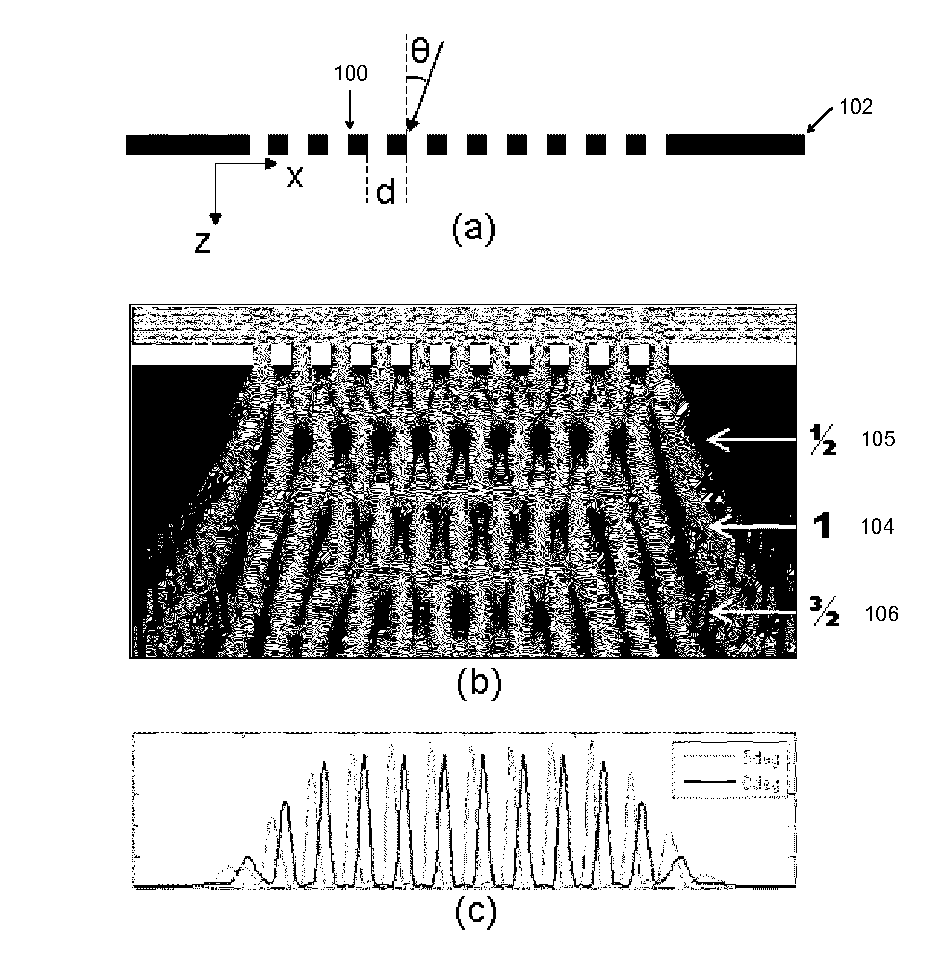
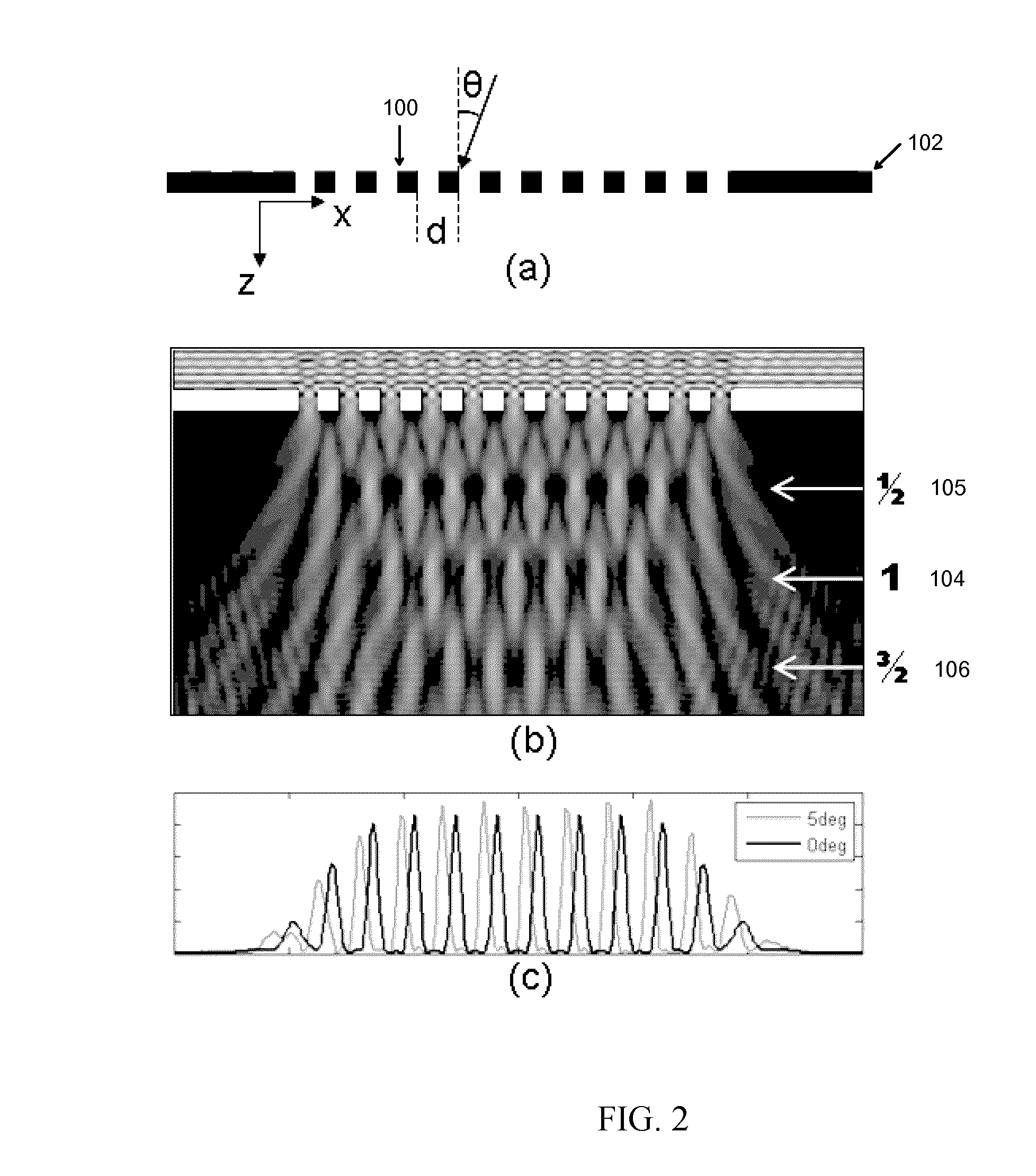
[0016]An embodied micron-scale device requires both a periodic diffracting structure to generate Talbot self-images and a structure for analyzing these self-images. By sizing the entire device to fit within an area of at most tens of microns on a side, spatial resolution may be achieved that is comparable with existing image sensors. In an illustrative aspect, the periodic diffracting structure will have several periods within this area to produce an operable periodic self-image. Thus the diffracting structure may have a period of only a few wavelengths. Contemporary planar photolithography techniques can easily achieve the resolution required to generate appropriate diffracting structures. Numerical modeling and simulation can accurately predict behavior for finite gratings built on a single-micron scale.

Problems solved by technology

However, this intensity map fails to capture incident angle, polarization angle, and other properties of light rays passing through the image plane.
Clearly, perfect determination of the plenoptic function for any practical scene is impossible.
However, all of these approaches require a significant number of parallel or moveable optical components to capture information about the light field beyond a simple intensity map.
Three-dimensional information is completely lost.
To date, macroscopic angle-detectors have been demonstrated in unmodified integrated circuit technology.
Pixel-scale angle-sensitive structures have been demonstrated on chip but require post-assembled arrays of microlenses, which significantly increase cost and complexity over the manufacture and use of standard imagers.
This approach has been reportedly used to perform a single angle measurement but is not well suited to deployment in imager arrays.

Method used


Image

  • Light field image sensor, method and applications
  • Light field image sensor, method and applications
  • Light field image sensor, method and applications

Examples


example 1

Using Light Field Data For Refocusing And Range Finding

[0099]One way to constrain the problem described above is to assume that s is the result of visual information at a particular focal depth, and finding the best estimate for what the image should look like if the detected light originated only in that plane. s now describes a plane with dimensions X×Y, such that s has X*Y=N2 entries. Since this is now actually less than the size of r, A is still not square, but is now “wider” than it is “tall” such that the problem is now-over defined. By using a pseudo-inverse, usually defined for over constrained systems as (ATA)−1AT, one can extract a best fit for s given r. If there is a reasonably good fit (as there will be if the focal plane chosen is the correct one), then this approach will yield a good approximation of the actual object scene. In particular, if the approximation of s is:

s′=pinv(A)r,

where pinv(A) is the pseudo-inverse of A, and given that A was chosen such that

r=As,

the...

example ii

Using Light Field Data For Extraction Of Sparse Fluorescent Sources

[0103]Another exemplary application pertains to imaging the three dimensional structure of fluorescing cells in tissue. Since the goal of such an application would be to be able to independently quantify the fluorescence of multiple cells at different focal planes, refocusing is not an appropriate approach. However, if one adds the two additional constraints: i) that all entries in s must be strictly positive (there is no such thing as negative fluorescence), and ii) that the fluorescent sources are relatively sparsely distributed in the volume being imaged, one may assume that the number of fluorescent cells is smaller than N2, the number of pixels. If this holds true, then one can find each of these sources iteratively and in order of brightness as follows:

[0104]a) correlate r with the expected response to each possible entry in s as:

c=rAT;

[0105]b) find the index, j, of s that correlates best with r (index of the m...


PUM


Abstract

An angle-sensitive pixel (ASP) device that uses the Talbot effect to detect the local intensity and incident angle of light includes two local diffraction gratings stacked above a photodiode. When illuminated by a plane wave, the upper grating generates a self-image at a selected Talbot depth. The second grating, placed at this depth, blocks or passes light depending upon incident angle. Several such structures, tuned to different incident angles, are sufficient to extract local incident angle and intensity. Arrays of such structures are sufficient to localize light sources in three dimensions without any additional optics.

Description

RELATED APPLICATION DATA[0001]The instant application claims priority to U.S. Provisional application Ser. No. 61 / 083,688 filed on Jul. 25, 2008, the subject matter of which is incorporated herein by reference in its entirety.FEDERALLY SPONSORED RESEARCH[0002]Not applicable.BACKGROUND[0003]1. Field of the Invention[0004]Embodiments of the invention are generally directed to the field of light field and light field image detection. More particularly, embodiments of the invention are directed to a lens-less, angle-sensitive pixel (ASP) device and to a lens-less light field image detector comprised of two or more of the lens-less ASP devices that can measure the intensity and direction angle of a light field to provide an image of the light field. Embodiments of the invention further include, without limitation, a pseudo-3-D CMOS, ASP imaging device, imaging methods associated with said device embodiments, and applications thereof.[0005]2. Related Art Discussion[0006]Conventional imagi...

Claims


Application Information

Patent Timeline
Patent Type & Authority Patents(United States)
IPC IPC(8): G02B27/42
CPCG01S3/782H01L27/1446G01N21/64G01B11/14G01N2201/062H01L27/146
Inventor MOLNAR, ALYOSHAWANG, ALBERT
Owner CORNELL UNIVERSITY
Why Eureka
Try Eureka