Level shifting circuit
a level shifting circuit and level shifting technology, applied in logic circuits, pulse automatic control, pulse technique, etc., can solve problems such as power waste, pump consumption, and multiple supply voltages that are associated with current leakage,
- Summary
- Abstract
- Description
- Claims
- Application Information
AI Technical Summary
Problems solved by technology
Method used
Image

Examples
Embodiment Construction
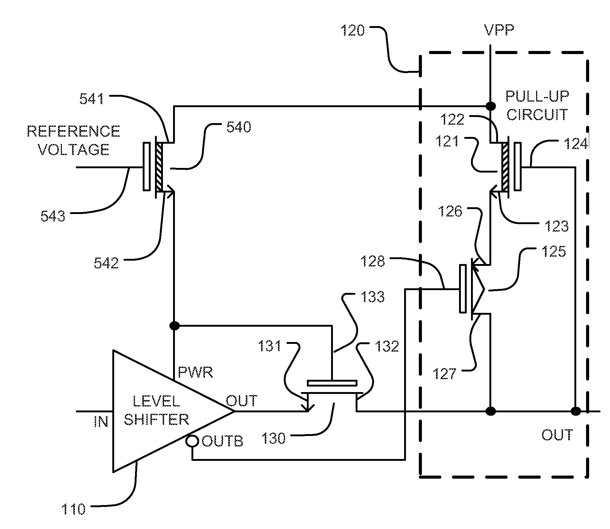
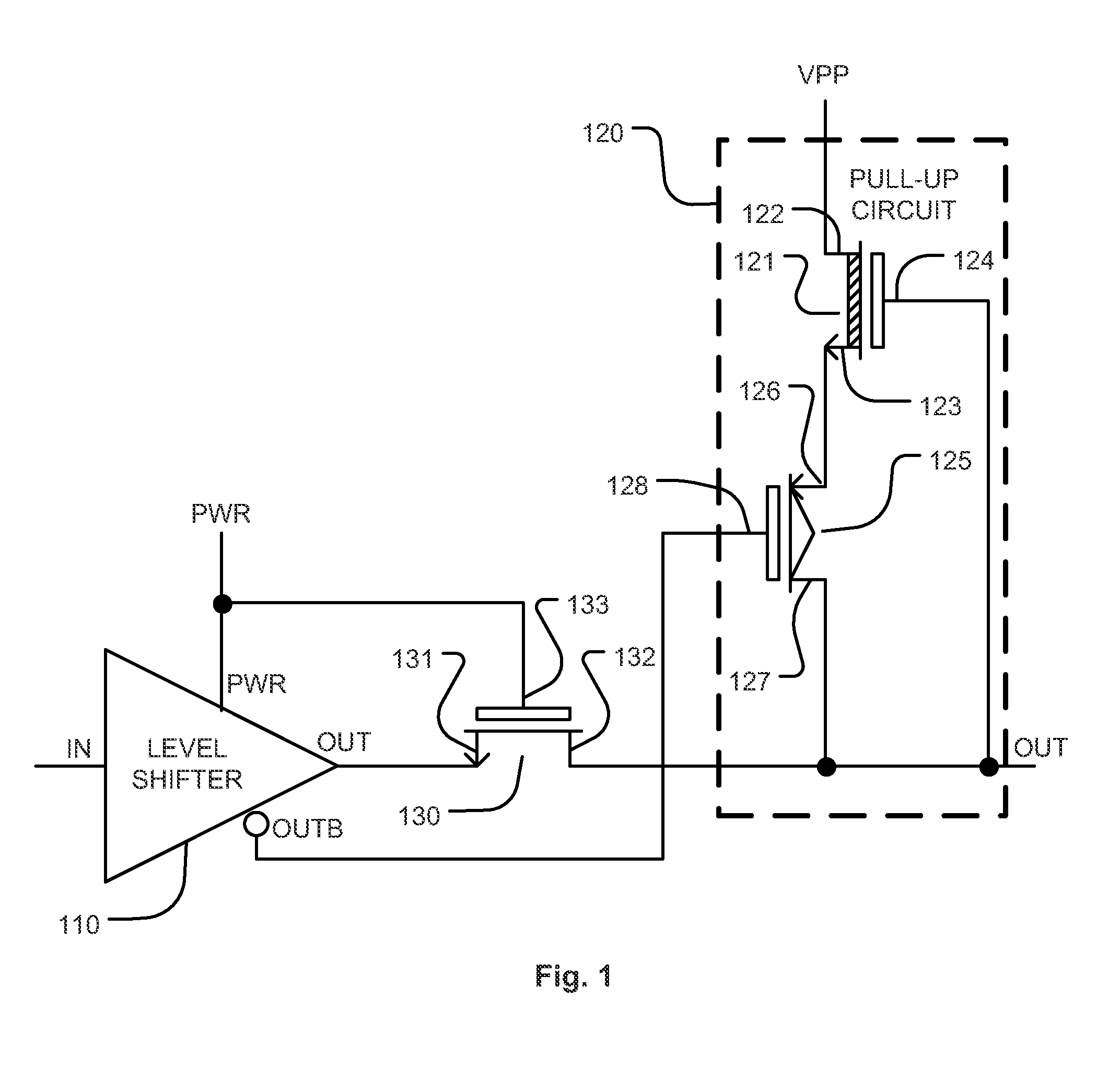
[0038]FIG. 1 shows a level shifting circuit with multiple stages receiving power from two supply voltages PWR and VPP. The supply voltages PWR and VPP can be generated by a low voltage pump and a high voltage pump respectively.
[0039]An early stage of the level shifting circuit which is a level shifter 110, is coupled to a later stage of the level shifting circuit which is a pull-up circuit 120.
[0040]The level shifter 110 receives power from the PWR supply voltage. The level shifter 110 receives an IN signal, and outputs the OUT signal and its complement OUTB signal. Because of the level shifter 110, there are different maximum voltages of the OUT signal and the IN signal of the level shifter 110. The maximum voltage of the OUT signal from the level shifter 110 is determined by the PWR supply voltage.
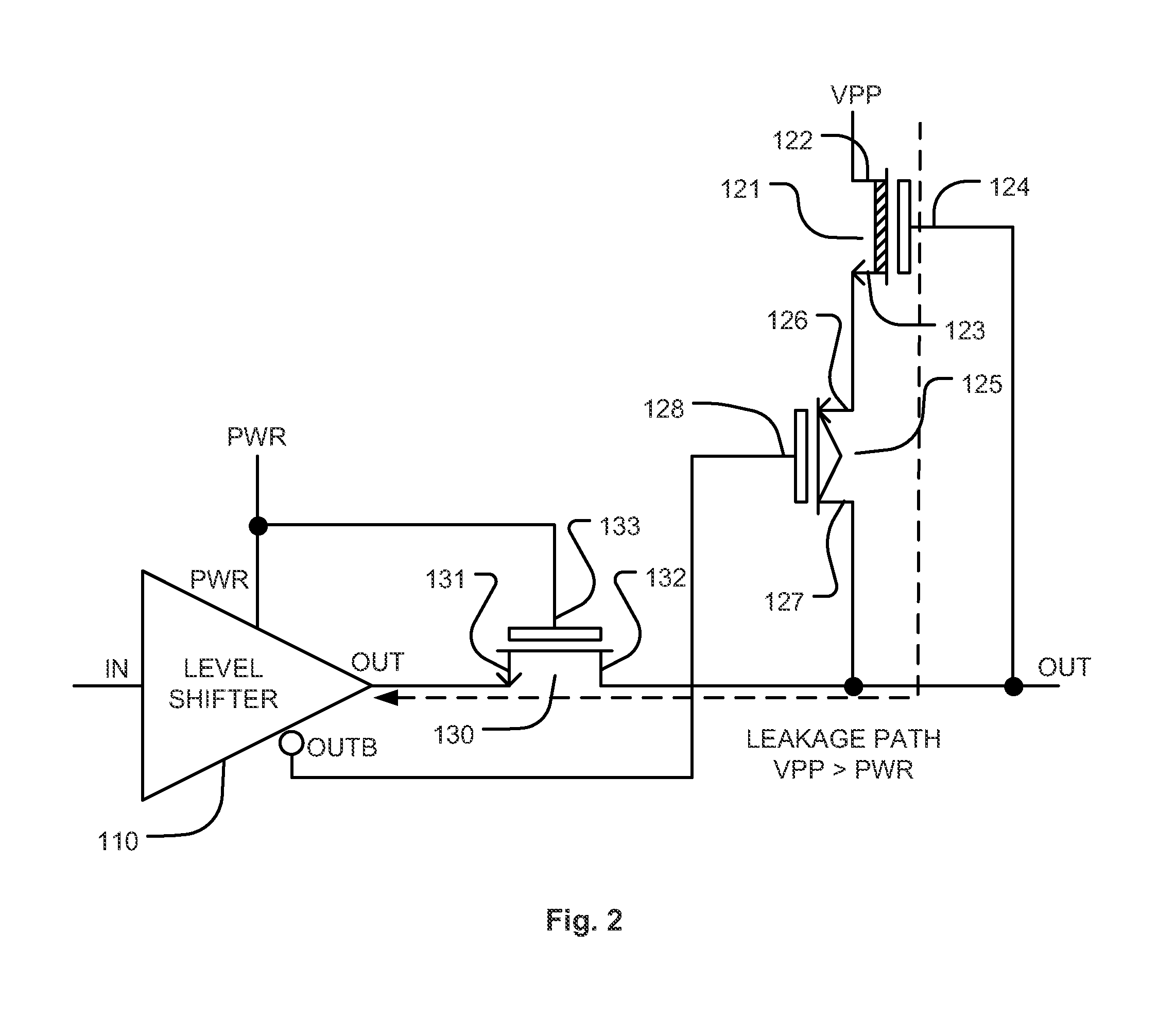
[0041]The pull-up circuit 120 includes a depletion mode n-type transistor 121 and a p-type transistor 125 that are coupled in series between supply voltage VPP and OUT of the pull-up cir...
PUM
 Abstract
Description
Claims
Application Information