Method and device for optimizing the compression of a video stream

a video stream and compression technology, applied in the field of video stream compression, can solve the problems of visual output noticeably worse, costing resources, and affecting the quality of the video stream, and achieve the effect of optimizing the resources used in the decoder and costing resources

Active Publication Date: 2013-09-10
NINTENDO EUROPEAN RESEARCH & DEVELOPMENT
View PDF9 Cites 0 Cited by
  • Summary
  • Abstract
  • Description
  • Claims
  • Application Information

AI Technical Summary

Benefits of technology

[0035]The implementation of the inventive method, as briefly described above, thereby makes it possible to optimize the resources used in the decoder by optimizing the encoding of the residual.
[0036]Owing to these measures, if the information added by the residual is insufficiently relevant or useful, the residual is not encoded in the feed. In this manner, for certain blocks, the decoding of the factors of the residual and the adding of the residual to the reconstructed block, which are costly in resources, are avoided.

Problems solved by technology

This prior art, in particular, has the disadvantage that the motion compensation factor decoding, compensation calculation and predicted block compensation steps are costly in resources.
However, in some cases, the visual output is noticeably worse.

Method used


Image

  • Method and device for optimizing the compression of a video stream
  • Method and device for optimizing the compression of a video stream
  • Method and device for optimizing the compression of a video stream

Examples


third embodiment

[0134]In a third embodiment shown in FIG. 5, during a step 501, the image to be encoded is broken down into blocks, and the blocks of the image to be encoded are saved to memory. The following steps, 502 to 516, are performed in succession for every block of the image to be encoded.

[0135]During a step 501, the motion estimation of the current block of the image to be encoded is performed, and at least one prediction is provided.

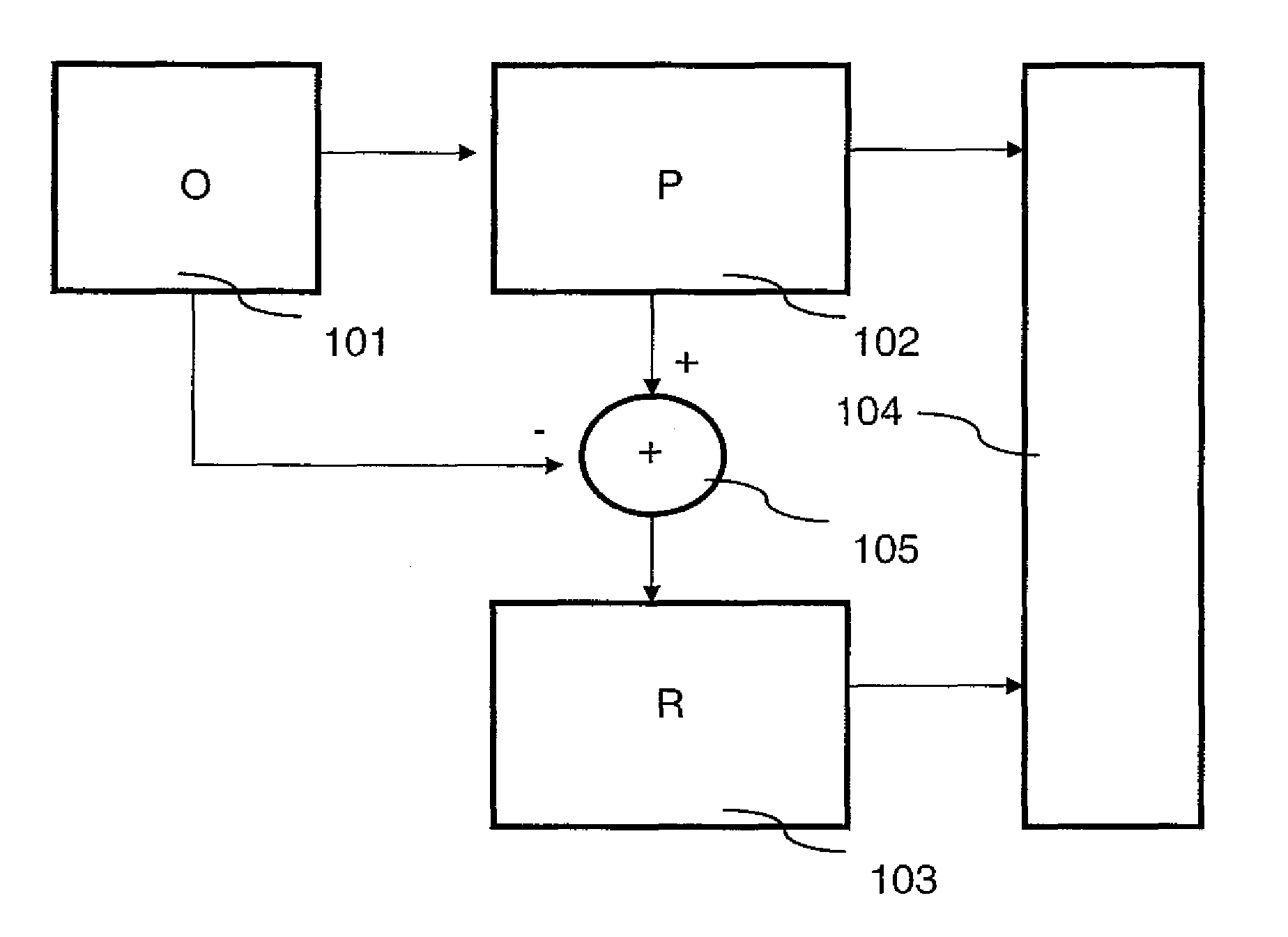
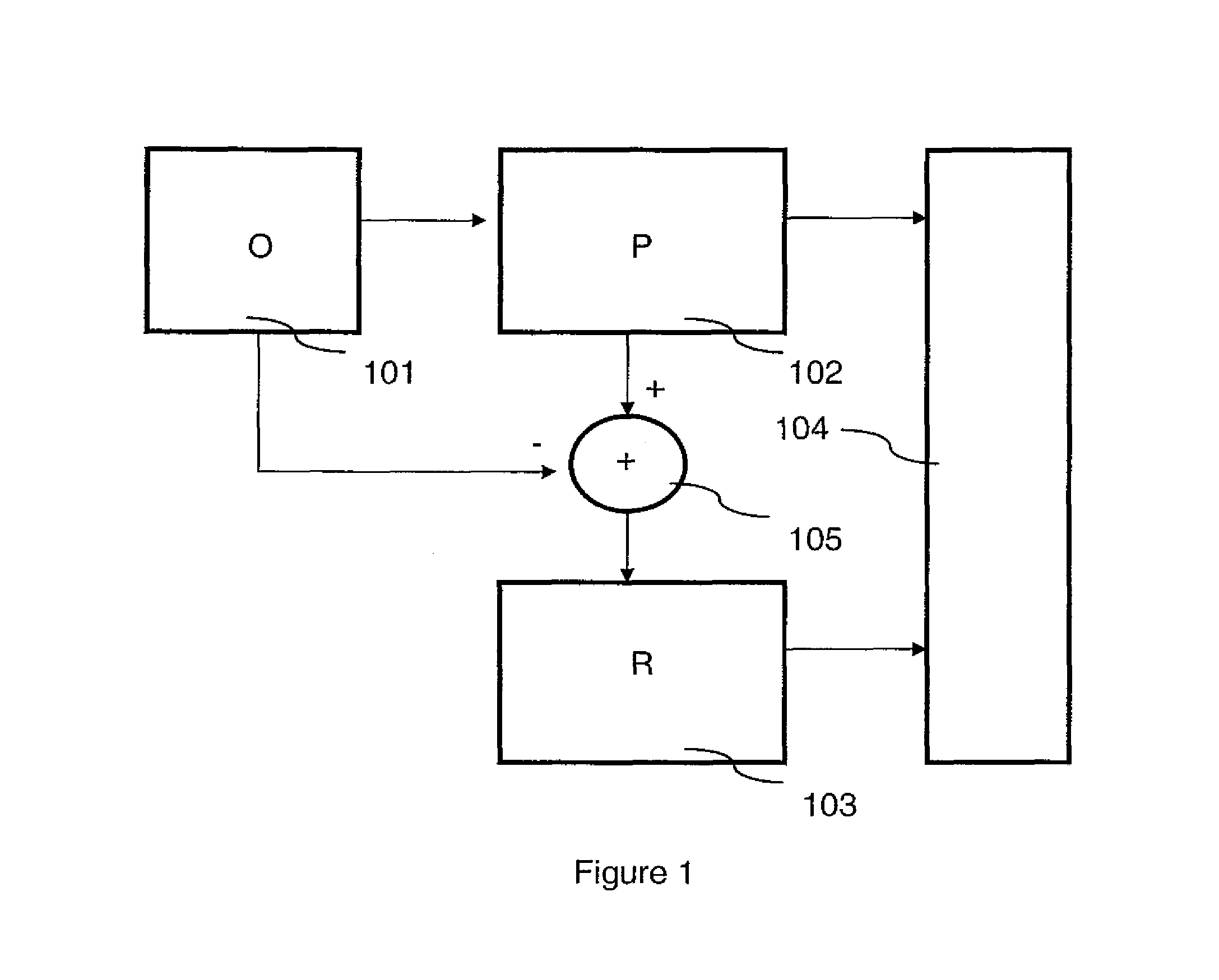
[0136]Next, during a step 503, the difference between the prediction and the block from the original image to be encoded is determined, and the results of this difference, known as the “residual,” are written to memory.

[0137]During a step 514, the distortion Dp and optionally the rate Rp that would be generated by the encoding of each prediction in the video stream are estimated, and Dp and optionally Rp are stored in memory.

[0138]During step 514, it is determined whether, for a given block, the residual must be transmitted to the decoding device. To that end...

fourth embodiment

[0149]In a fourth embodiment, shown in FIG. 6, the image to be encoded is broken down into blocks, and stored in a memory area, during a step 601. The following steps, 602 to 616, are performed in succession for every block of the image to be encoded.

[0150]During a step 602, the motion estimation of the current block of the image to be encoded is performed, and at least one prediction is provided.

[0151]During a step 614, the rate Rp and optionally the distortion Dp that would be generated by the encoding of each prediction within the video feed are calculated, and Rp and optionally Dp are saved to memory. During step 614, it is determined whether a motion compensation, or a residual must be encoded, in the following manner: the decision parameter

RD1=Rp*ε+Dp

[0152]is calculated, where:[0153]Rp is the rate of the predicted block (optional),[0154]Dp is the distortion of the predicted block, and[0155]ε, a positive value, is set by the programmer or user of the coder / decoder, or is confi...


PUM


Abstract

A method and device for compressing at least a portion of a video image such that a compressed video stream includes, or does not include, an encoding of a residual depending on whether it is advantageous to do so in terms of costs in rate and in distortion. The size of the video stream and resources needed for decompression are optimized through encoding only the most relevant data in the video stream. If the information added by the residual is insufficiently relevant or useful, the residual is not encoded. Factors associated with the residual are only encoded if use of the residual limits the distortion in a satisfactory manner and if the encoding of the associated factors does not generate too high a rate. Use of the method makes it possible to optimize resources needed for a decoder by optimizing the encoding of the residual.

Description

CROSS REFERENCE TO RELATED APPLICATIONS[0001]The present application is based on and claims priority to International Application PCT / EP2007 / 009315 filed on Oct. 26, 2007 and French Patent Application No. 06 / 09432 filed on Oct. 27, 2006, the contents of which are hereby incorporated by reference in their entirety.BACKGROUND OF THE INVENTION[0002]This invention pertains to a method and device for compressing portions of images. In particular, it applies to encoding images and sequences of images, especially for the purpose of transmitting them over a computer network, such as the Internet, or for storing them on a digital information medium. This method and device may be integrated into any system with the ability to compress and then decompress any portion of an image on all hardware platforms.[0003]Certain video encoding methods use predictive methods with residual encoding. FIG. 1 depicts a device implementing such a method, in the form of a block diagram. A prediction made by the...

Claims


Application Information

Patent Timeline
Patent Type & Authority Patents(United States)
IPC IPC(8): H04N7/32G06K9/36
CPCH04N19/00569H04N19/50H04N19/176H04N19/147H04N19/36H04N19/132H04N19/19H04N19/507H04N19/103
Inventor LARRIEU, JEROME
Owner NINTENDO EUROPEAN RESEARCH & DEVELOPMENT
Why Eureka
Try Eureka